Section 10 STEERING SYSTEM
Subsection 01 (STEERING SYSTEM)
F22K21A
Ensure handlebar adjuster works adequately.
Secure steering cable ball joint no. 31 to stem arm
lever.
CAUTION: Ensure the ball joint is parallel to the
stem arm within ±10°.
Properly install remaining components.
Handle Grip and Grip Insert
When installing the grip insert no. 9 in the handle-
bar no. 1, ensure that it is properly inserted in the
slot at the end of the handlebar tubing.
F02K0JA
1
TYPICAL
1. Grip insert
Install grip no. 6 on handlebar no. 1 matching it to
the notch in the handlebar.
Install flat washer and screw no. 8.
Torque screw to 7 N•m(62lbf•in).
Install cap no. 7.
F02K0KA
1
2
4
53
TYPICAL
1. Grip insert
2. Grip
3. Flat washer
4. Screw. Torque to 7 N•m(62lbf•
in)
5. Cap
CAUTION: Ensure to install flat washer other-
wise screw will damage grip end.
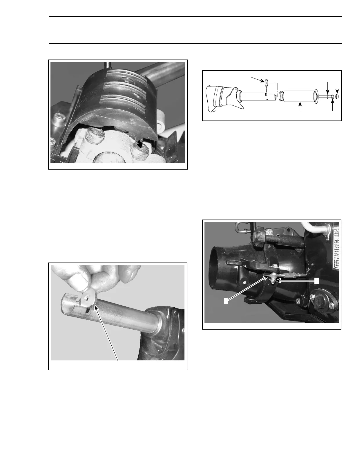
Ball Joint
Secure the steering cable ball joint no. 33 to the
nozzle as per following illustration.
CAUTION: Ensure the ball joint is parallel to the
nozzle arm within ±10°.
F22K24A
1
2
1. Ball joint below steering arm
2. Torque nut to 7 N•m(62lbf•
in)
Finalizing the Assembly
Install remaining components.
Ensure steering works adequately.
Ensure throttle cable works adequately in all han-
dlebar adjustment position and in all steering pole
position.
Perform throttle cable adjustment. Refer to EN-
GINE MANAGEMENT.
smr2005-066 301