Section 10 STEERING SYSTEM
Subsection 02 (OFF-POWER ASSISTED STEERING (O.P.A.S.))
To adjust the tie-rod, remove tie-rod screw no. 3
and turn tie-rod fitting no. 5. Place tie-rod screw
in its place and measure again. Repeat the proce-
dure until the distance is reached.
When the adjustment is done, torque the tie-rod
screw to 4.5 N•m(40lbf•in).
Install socket screw no. 2 andtorqueitto2.7N•m
(24 lbf•in).
NOTE: The socket screw no. 2 should be turned
2 - 3 turns before using a tool.
Installation
Installation is the reverse process of removal.
Install the tie-rod screw no. 3. Do not torque yet.
Perform the tie-rod fitting adjustment. See above.
Cylinder Support
Removal
Removal procedure for RH and LH cylinder sup-
port assembly is same.
Remove side vane as mentioned above.
NOTE: To disassemble the cylinder, it is not re-
quired to remove it from vehicle. See DISASSEM-
BLY AND ASSEMBLY procedure.
Unscrew tie rod fitting no. 5 from tie rod no. 7.
Unscrew 4 socket screws no. 8. Discard them.
F18K0PA
1 1
1. Socket screws
Disassembly and Assembly
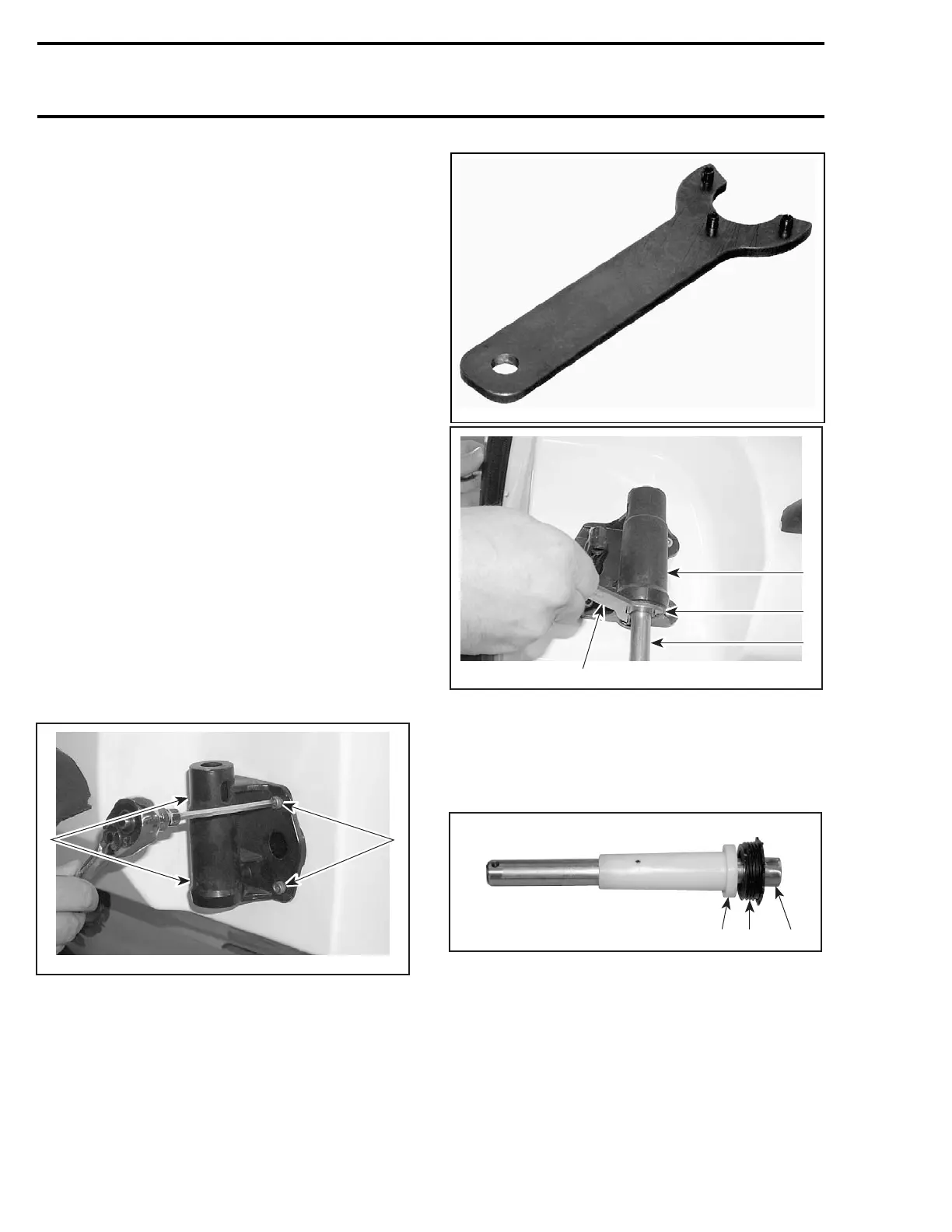
Unscrew cylinder cap no. 9 using the O.P.A.S.
cylinder nut wrench (P/N 529 035 840).
529035840
4
F18K0NA
2
1
3
1. Cylinder cap
2. Cylinder support
3. Pivot rod
4. O.P.A.S. cylinder nut wrench
Remove cylinder assembly out of cylinder sup-
port.
1
F19J0DA
2
3
1. Pivot rod
2. Spacer
3. Cylinder cap assembly
Check pivot rod no. 4 for cracks or scratches. Re-
place pivot rod, if necessary.
Installation
The installation is the r
everse of the removal pro-
cedure. However, pay a
ttention to the following
details.
308 smr2005-067