Section 03 ENGINE SYSTEM
Subsection 03 (REMOVAL AND INSTALLATION)
F01D7OA
TYPICAL — GTI RFI SHOWN
Using a chain block, a hoist or other suitable equip-
ment, slightly lift engine to ease the remaining
component removal.
CAUTION: Take care not to damage cable or oil
injection hoses.
Remove rear engine support bolts then remove
engine support from engine.
1
2
smr2005-049-008_a
TYPICAL
1. Rear support
2. Engine support bolts
All Engines
Lift up engine slowly until oil injection hoses can
be reached.
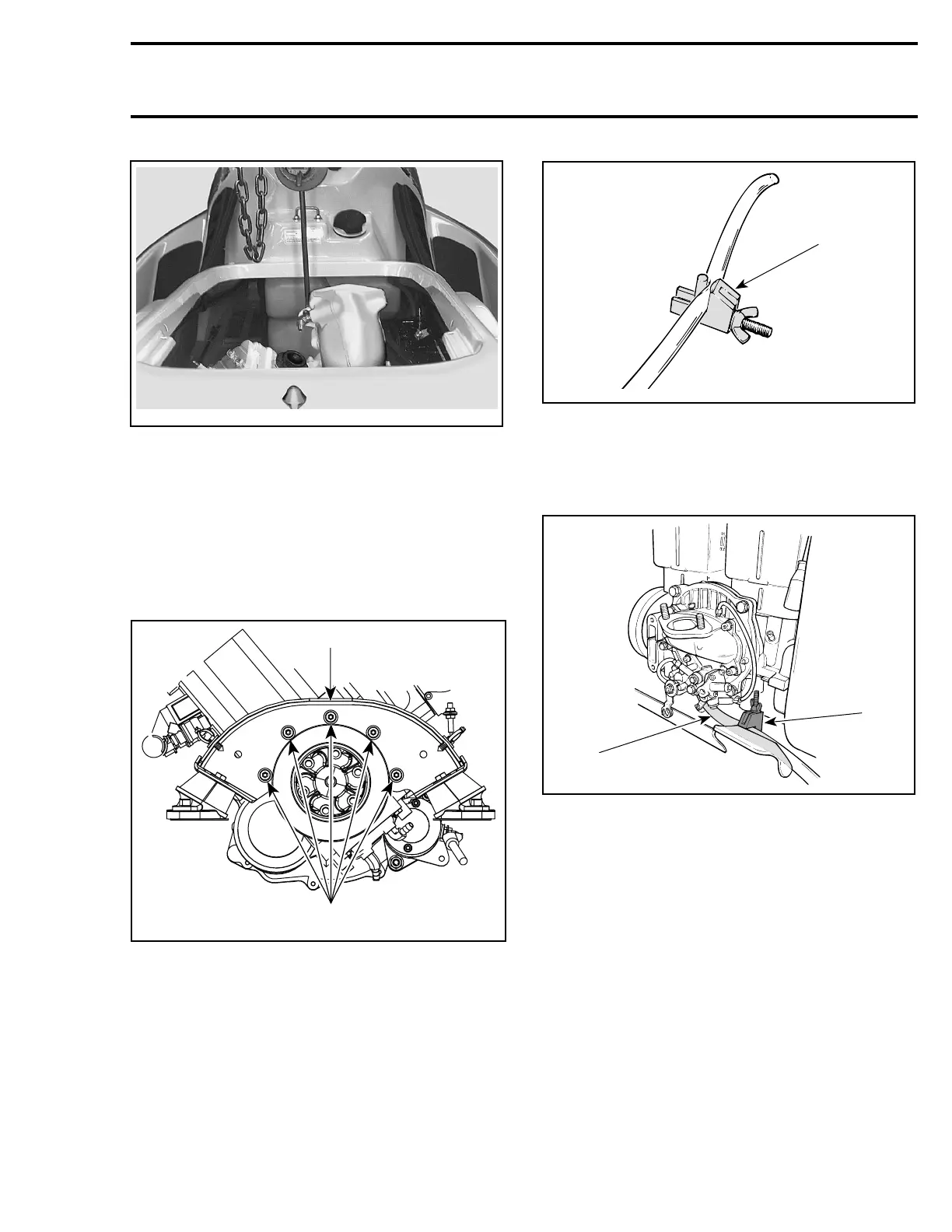
Install a small hose pincher (P/N 295 000 076) to
oil supply hoses of oil injection pump and rotary
valve shaft; then, disconnect hoses.
A01B2JB
1
TYPICAL
1. Small hose pincher
Install another small hose pincher (P/N 295 000
076) to oil return hose of rotary valve shaft; then,
disconnect hose.
F01D3ZA
2
1
TYPICAL — 717 ENGINES
1. Rotary valve oil supply line
2. Hose pincher installed
smr2005-049 63