The signals shown in Figure 6-28 in DIGSI 5 information routing have the following relationship:
•
In terms of switching authority and switching mode, the respective key switch position serves as the
input signal and the input signals in the matrix.
•
The state of the switching authority and switching mode is indicated by corresponding output signals.
•
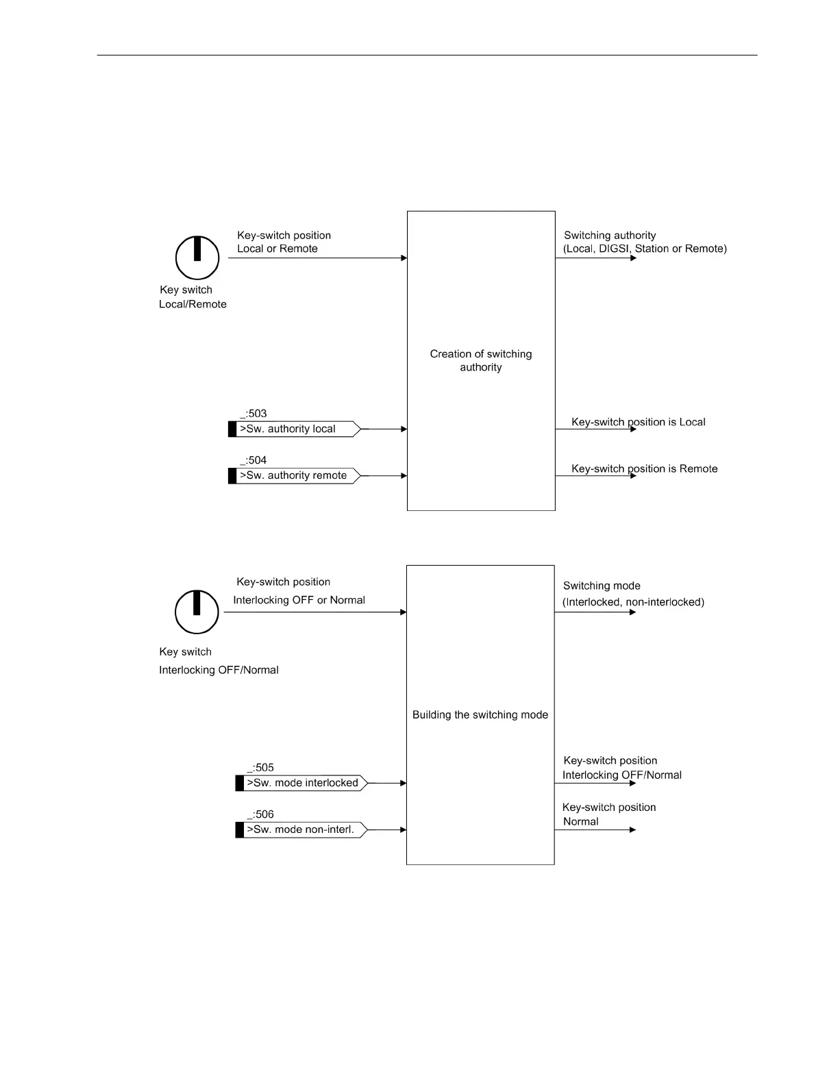
The Switching authority and Switching mode functions link the input signals and in this way establish
the output signals (see Figure 6-29 and Figure 6-30).
[dwhoheit-260511-01.tif, 1, en_US]
Figure 6-29 Establishing Switching Authority
[dwmodsch-020513-01.tif, 1, en_US]
Figure 6-30 Establishing Switching Mode
In the case of both functions, the input signals overwrite the state of the key switch. This allows external
inputs to also set the switching authority or switching mode, if desired (for instance, by querying an external
key switch).
Control Functions
6.3 Control Functionality
SIPROTEC 5, High-Voltage Bay Controller, Manual 339
C53000-G5040-C015-9, Edition 11.2017
 Loading...
