3-11
Chapter 3 Installing 4100ES MINIPLEX Components
RUI Wiring
Overview The TIC connects to the CPU via the RUI interface. Wire from the RUI interface to each TIC.
The wiring may be Class A or Class B.
RUI/RUI+
Specifications
• Output: 24V @ 130mA (RUI), 500 mA (RUI+); 32V maximum (RUI); 25.2V max
(RUI+).
• Data Rate: 9,600 bits per second.
• 35.5 ohms maximum wiring impedance; 2500 feet maximum wiring distance.
Wiring
Configurations
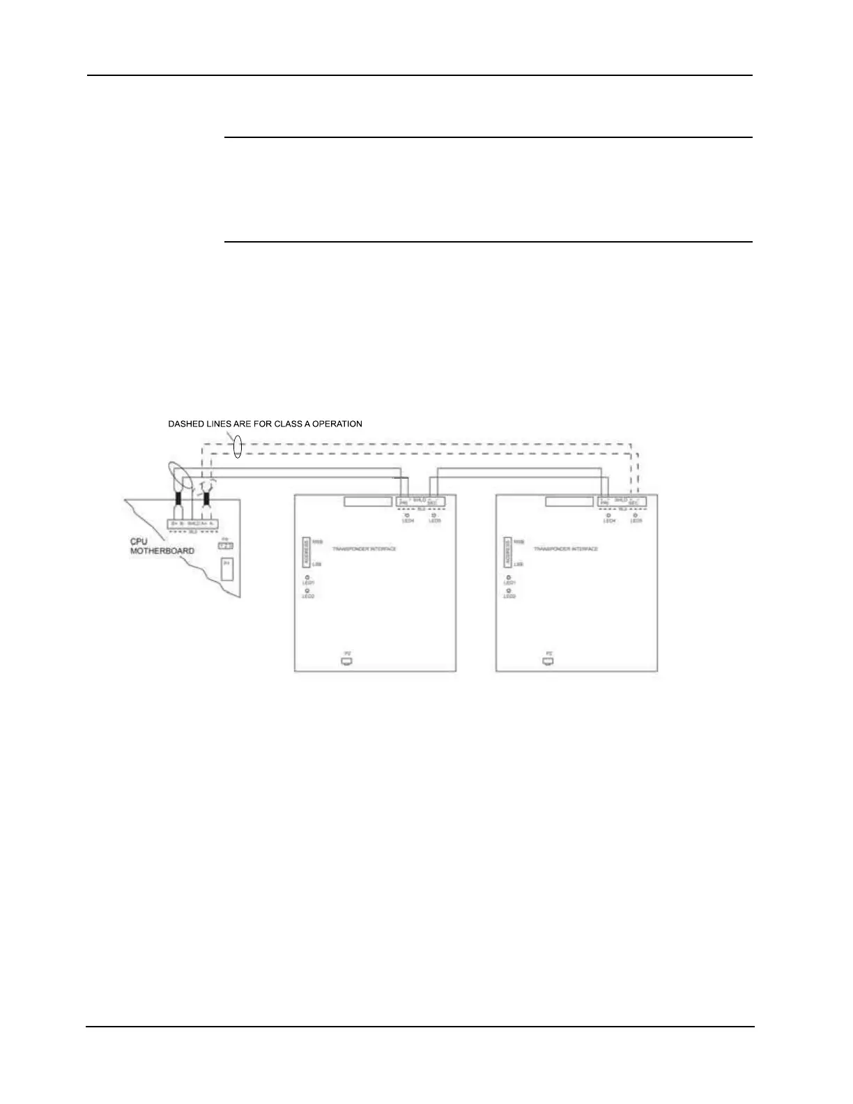
Class A wiring allows transponder cabinets to communicate with the FACP even in the event
of a single open circuit somewhere in the loop. Class A wiring requires that two wires are
routed from the CPU motherboard to each TIC, and then back again to the CPU motherboard.
Class B wiring allows “T” tapping, and therefore requires less wiring distance per installation
than Class A.
Figure 3-4 depicts both types of wiring.
Figure Notes:
1. Wire size must be between 18 AWG and 12 AWG.
2. The maximum wiring distance is 2,500 feet (762 m).
3. The maximum cable load is 10,000 feet (3,048 m).
4. Maintain correct polarity on terminal connections.
5. Do not loop wires under terminals.
6. Shield is optional if the RUI+ Master Motherboard is used.
7. Twisted wire is required for RUI. Twisted wire is recommended for improved noise immunity for
RUI+.
Figure 3-4. TIC Wiring to the Host Panel