8-2
Chapter 8 EPS and IDNet 2 Wiring
EPS Wiring Overview
General Wiring
Guidelines
• Conductors must test free of all grounds.
• All wiring must be done using copper conductors only, unless noted otherwise.
• If shielded wire is used:
- the metallic continuity of the shield must be maintained throughout the entire cable
length.
- the entire length of the cable must have a resistance greater than 1 Megohm to
earthground.
• Underground wiring must be free of all water.
• In areas of high lightning activity, or in areas that have large power surges, the 2081-9027
Transient Suppressor should be used on monitor points.
• Wires must not be run through elevator shafts.
• Splicing is permitted. All spliced connections must either be soldered (resin-core solder),
crimped in metal sleeves, or encapsulated with an epoxy resin. When soldering or crimped
metal sleeves are used, the junction must be insulated with a high-grade electrical tape that is
as sound as the original insulating jacket. Shield continuity must be maintained throughout.
• A system ground must be provided for earth detection and lightning protection devices. This
connection must comply with approved earth detection per NFPA780.
• Only system wiring can be run together in the same conduit.
Power-Limited
Guidelines
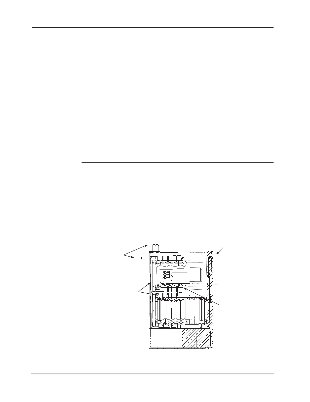
• Non-power limited field wiring (AC power, batteries, City connection) must be installed and
routed in the shaded areas shown in Figure 8-1.
• Power-limited field wiring must be installed and routed in the non-shaded shown in Figure
8-1, with the exception of City wiring.Excess slack should be kept to a minimum inside the
back box enclosure. The wiring should be neatly dressed and bundled together using wire
ties. Anchor power-limited wiring to tie points.
• Tie the wiring located between bays to the internal wiring troughs, if applicable.
• When powering remote units or switching power through relay contacts, power for these
circuits must be provided by a power-limited power supply listed for fire-protective
signaling use.
Figure 8-1. Power-Limited Wiring Guidelines
Conduit Entrance for
Non-Power Limited
Wiring
Conduit Entrance for
Power-Limited Wiring
Non-Power Limited
Wiring (Route in
Shaded Area Only)
Power-Limited Wiring
Tie Point
(Location
May Vary)