2-32
Chapter 2 Installing FACP Components
Step 7. Interconnecting Modules and Bays (continued)
Power
Distribution
Module
Connections
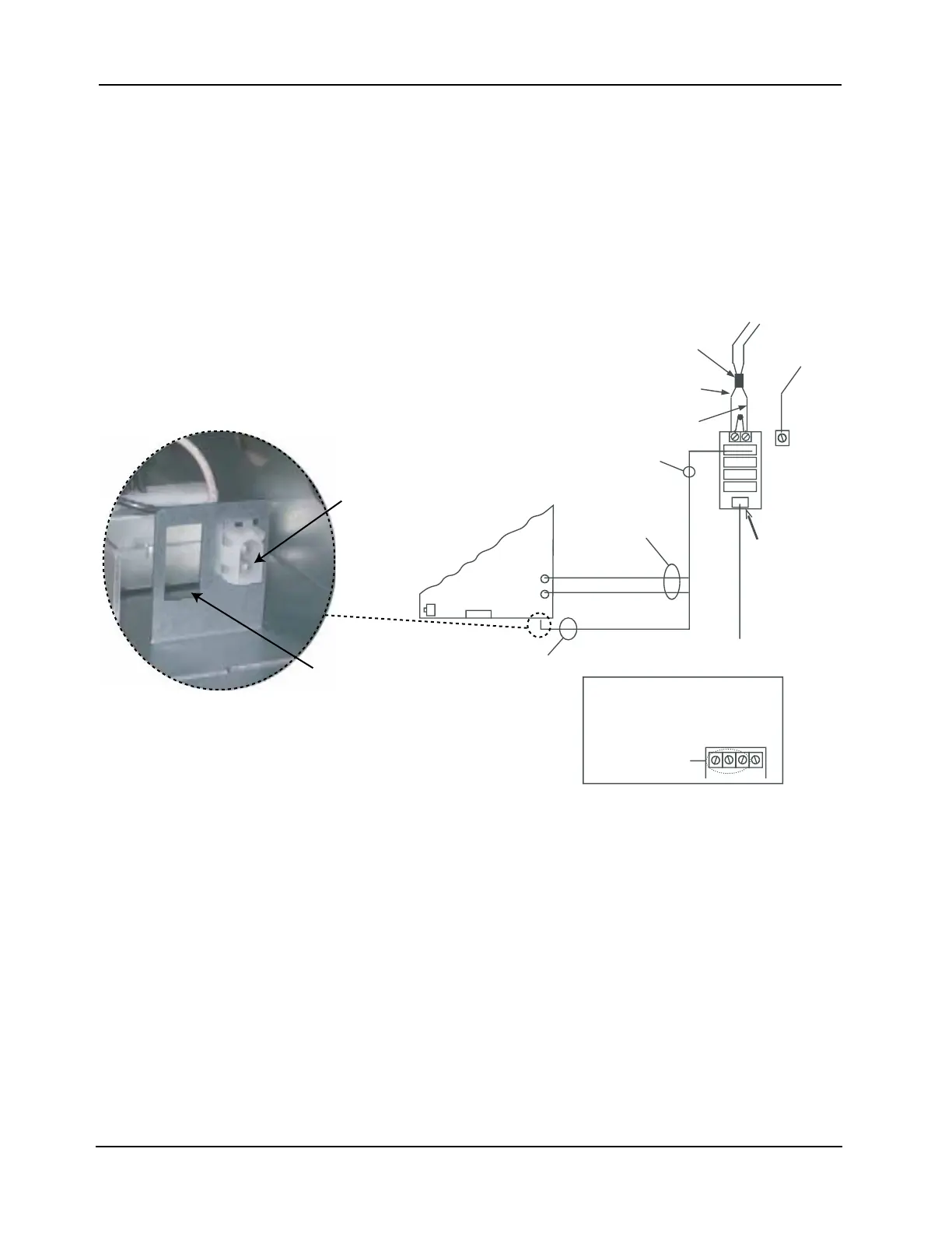
4. Connect the PDM to the power supply using Harness 734-012 for 120 V systems (734-013
for 220/230/240 V versions).
• Feed red and black wires through the side rail to the front of the power supply to prevent
wire damage when the front panel is inserted.
• Connect the separate red and black wires (with yellow female terminations) to plugs P2
(black) and P3 (red) on the EPS and plugs P5 (black) and P4 (red) on the SPS or RPS.
• Connect the white and black wires, which terminate together in a white snap-on connector,
to the bulkhead connector at the bottom of the EPS, SPS or RPS assembly, as shown in
Figure 2-34.
Figure 2-34. FACP Power Supply Assembly Connector (EPS shown)
Continued on the next page
P1
P2
P3
P4
P5
EPS
120 V TO TRANSFORMER
THROUGH BULKHEAD
CONNECTOR
RED WIRE
BLACK WIRE
P2
P3
BATTERY
HARNESS
FUSED AT 20 A
HARNESS 733-015
TO 24 V BATTERY
HARNESS
(734-257)
(734-258)*
GROUND
BACK BOX
GROUND
SCREW
*220/230/240 V PART NUMBERS
APPEAR IN ITALICS.
CAV022
C
AV
03
2
C
AV
042
T
U
EN
50/60 Hz
2.3 A
566-248
PDM TERMINAL
BLOCK
120 V
NEUTRAL
120 VAC
50, 60 Hz, 4.6 A
FERRITE
BEAD
PDM
(566-246)
(or 566-248;
see below)*
Bottom view
of the EPS assembly
Bulkhead connector
Second bulkhead
connector here in
220/ 230/240 V
version