7-6
Chapter 7 EPS with IDNet 2
Connections
Connection to the
Power
Distribution
Module
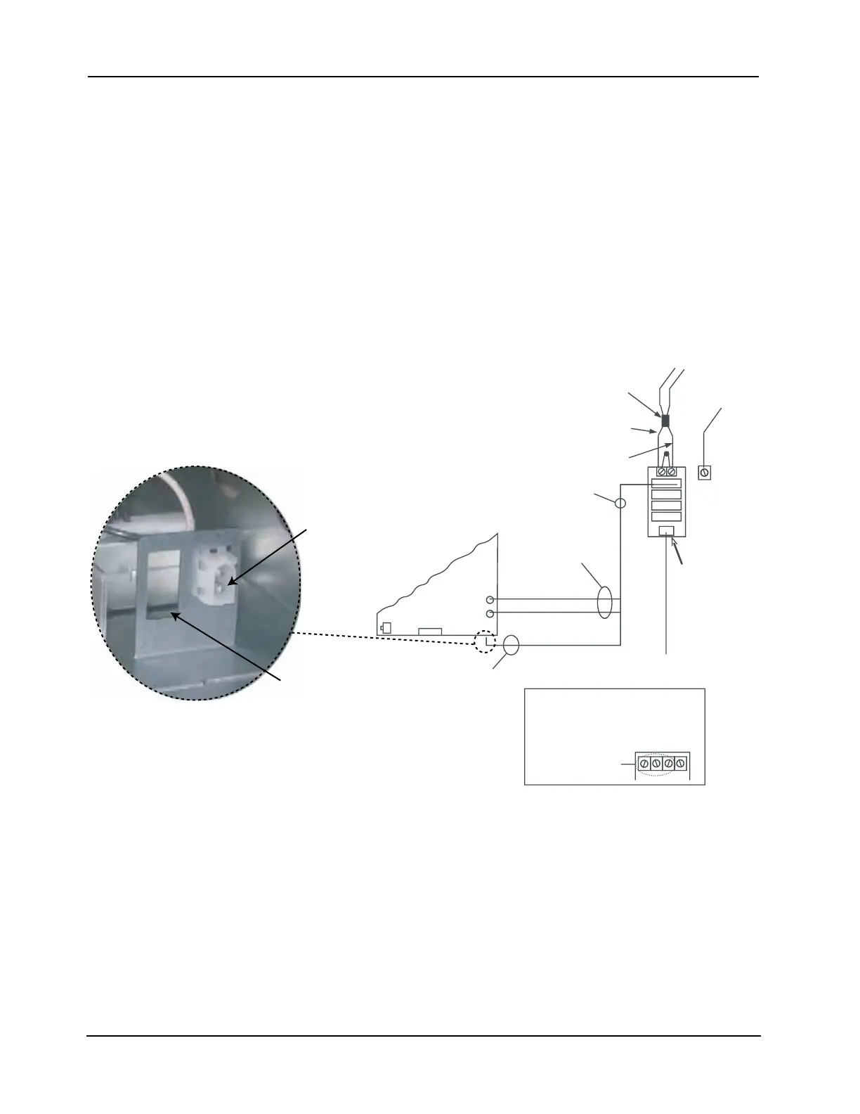
The EPS is powered by the Power Distribution Module (PDM). The PDM takes power directly
from a dedicated AC line and the two backup batteries, and distributes power to each bay in the
cabinet.
To connect the EPS to the PDM using Harness 734-257:
1. Ensure that the PDM is connected to an incoming 120 VAC power source. Keep the AC
wires to the right side of the cabinet, in the non-power-limited area, and at least one inch
away from all other wires.
2. Connect the harness connector to the PDM.
3. Connect the separate Red and Black wires (with Yellow female terminations) to Plugs P2
(Black) and P3 (Red) on the EPS.
4. Connect the White and Black wires, which terminate together in a White snap-on connector,
to the bulkhead connector at the bottom of the EPS assembly.
Figure 7-6. PDM/Battery Connections
P1
P2
P3
P4
P5
EPS
120 V TO TRANSFORMER
THROUGH BULKHEAD
CONNECTOR
RED WIRE
BLACK WIRE
P2
P3
BATTERY
HARNESS
FUSED AT 20 A
HARNESS 733-015
TO 24 V BATTERY
HARNESS
(734-257)
(734-258)*
GROUND
BACK BOX
GROUND
SCREW
*220/230/240 V PART NUMBERS
APPEAR IN ITALICS.
CAV022
C
AV
03
2
C
AV
042
T
U
EN
50/60 Hz
2.3 A
566-248
PDM TERMINAL
BLOCK
120 V
NEUTRAL
120 VAC
50, 60 Hz, 4.6 A
FERRITE
BEAD
PDM
(566-246)
(or 566-248;
see below)*
Bottom view
of the EPS assembly
Bulkhead connector
Second bulkhead
connector here in
220/ 230/240 V
version