8-8
Chapter 8 EPS and IDNet 2 Wiring
EPS Wiring to Devices (continued)
Calculating Class
B wiring with
Isolators
When using Isolators, the maximum wire distance of each of these SLC branches from panel to
any device is the smaller of the values obtained from Table 8-2, and the Equation 1. See Table
8-3 for the ohms per 1000 ft.
• Add the alarm loads of all the devices on an SLC wire branch and apply to Equation 1.
• Add the unit loads for all devices on an SLC wire branch and the number of isolators and
apply to Table 8-2.
Maximum wire resistance protected by 1 isolator is 1.5 ohm (total, both wires).
Wire the devices as instructed in the “Class B Wiring to IDNAC Devices” section.
.
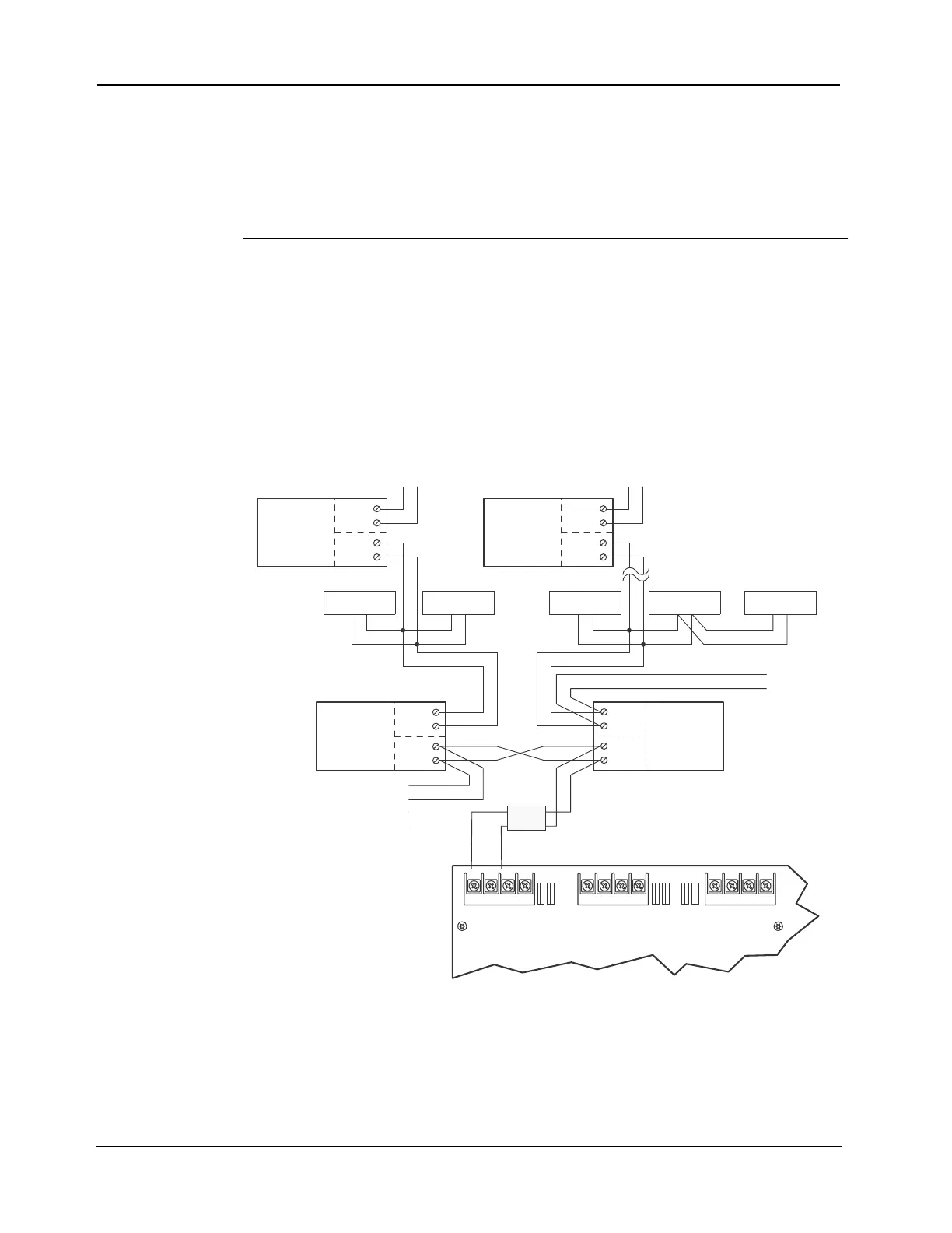
Figure 8-4. Class B Wiring With Isolators
Equation 1: Maximum SLC Wire Branch Length Based on Appliance Alarm Current Load
Distance (feet) = 6V - (.1 ohm * number of isolators on branch * branch alarm amps)
2 * (resistance per foot) * (branch alarm amps)
+ + - -
+ + - -
+ + - -
IDNAC1 IDNAC2 IDNAC3
TO OTHER
DEVICES
APPLIANCE
TO OTHER
DEVICES
TO OTHE
DEVICES
PORT
1
4905-9929
ISOLATOR
PORT
2
PORT
1
4905-9929
ISOLATOR
PORT
2
PORT
1
4905-9929
ISOLATOR
PORT
2
PORT
1
4905-9929
ISOLATOR
PORT
2
APPLIANCE APPLIANCE APPLIANCE APPLIANCE
Ferrite
Bead