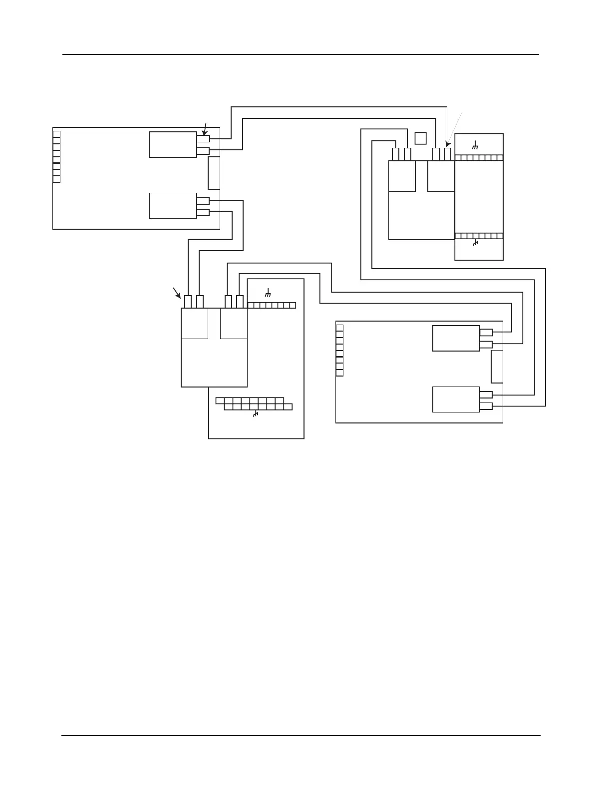
Figure 4-15. Fiber Optic, Style 7 Wiring
FD4-848-2
Notes:
1. Refer to general wiring precautions in this chapter, as well as Field Wiring Specifications: document 900-082 for 4100;
900-242 for 4100ES. For specific information about fiber optic wiring, refer to the 900-143 Fiber Tutorial.
2. The maximum distance between nodes when using the fiber communication path is dependent upon the fiber’s
multimode graded index: 10,000 feet (3,048 m) for 50/125 fiber; 15,000 feet (4,572 m) for 62.5/125 fiber. The maximum
cable O.D. is 0.118 (3 mm). Reference document 900-143 for other fiber sizes.
3. ST connectors with long strain relief boots are to be used with the fiber optic cable.
4. On assembly 565-274, JW1 and JW2 must be installed. Jumper plugs must not be installed on P5-P8.
5. Cable clamps supplied with 748-531 are used to secure the fiber cable.
OV2
L-
L+
EARTH
EARTH
OV1
R-
R+
TB2
NETWORK
INTERFACE
ASSY
565-411
0R
566-826
FIBER
OPTION
ASSY*
FIBER
OPTION
ASSY*
FIBER
OPTION
ASSY*
XMT
XMT
XMT
RCV
RCV
FIBER
OPTION
ASSY*
XMT
RCV
RCV
LEFT PORT
RIGHT PORT
TB1
PORT
LEFT
RIGHT
NETWORK INTERFACE
(DAUGHTER CARD)
ASSY 565-409 OR
566-793
4100
FIBER
OPTION
ASSY*
XMT RCV
FIBER
OPTION
ASSY*
XMT RCV
PORT
LEFT
RIGHT
NETWORK INTERFACE
(DAUGHTER CARD)
ASSY 565-409 OR
566-793
4100
4020
OV2
L-
L+
EARTH
EARTH
OV1
R-
R+
TB2
NETWORK
INTERFACE
ASSY
565-432
0R
566-825
FIBER
OPTION
ASSY*
FIBER
OPTION
ASSY*
XMT
XMT
RCV
RCV
LEFT PORT
RIGHT PORT
TB1
4002
TB1
TB2
MOTHERBOARD
ASSY
565-275
8
8
7
7
6
6
5
5
4
4
3
3
2
2
1
1
L
-
L
+
+
R
-
R
I
V
0
O
V
2
TB1
TB2
MOTHERBOARD
ASSY
565-274
8
8
7
7
6
6
5
5
4
4
3
3
2
2
1
1
L
-
L
+
+
R
-
R
I
V
0
O
V
2
9
10 11 12
13
14 15 16
7
* FIBER OPTION ASSY
565-261, 566-376, or 746-109
CAN BE USED
SEE NOTE 5
SEE NOTE 5
SEE NOTE 5