EasyManuals Logo

Simplex 4100ES Installation Guide

Simplex 4100ES
262 pages
To Next Page IconTo Next Page
To Previous Page IconTo Previous Page
Page #79 background imageLoading...
Page #79 background image
2-35
Chapter 2 Installing FACP Components
Step 7. Interconnecting Modules and Bays (continued)
SPS Basic Bay-
To-Bay
Interconnections
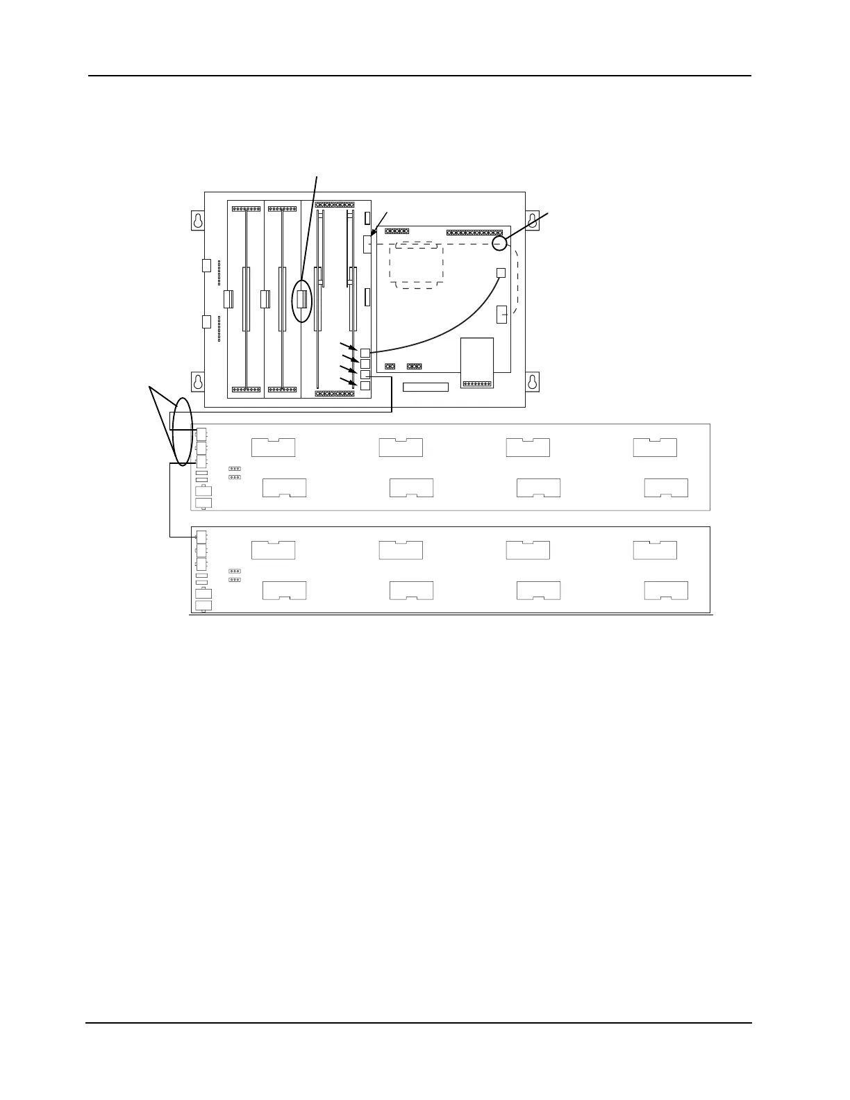
Figure 2-36 shows the interconnections between three bays in a host panel.
Figure 2-36. Bay-to-Bay Interconnections
For information on remote expansion bays, refer to Appendix B.
4100 POWER DISTRIBUTION INTERFACE
ASSY 566-084
4100 POWER DISTRIBUTION INTERFACE
ASSY 566-084
HARNESS
734-008
P8
733-996
HARNESS
(LEGACY SYSTEMS)
P1
P1
P2
P3
P4
P5
P6
P7
P1
P2
P3
P4
P5
P6
P7
J1/P3
P10
P2
P3
P4
P6

Table of Contents

Other manuals for Simplex 4100ES

Questions and Answers:

Question and Answer IconNeed help?

Do you have a question about the Simplex 4100ES and is the answer not in the manual?

Simplex 4100ES Specifications

General IconGeneral
TypeFire Alarm Control Panel
DisplayLCD
Battery BackupYes
Model4100ES
ManufacturerSimplex
Communication ProtocolOptional Ethernet
Signaling Line Circuits (SLCs)Up to 10
Notification Appliance Circuits (NACs)Up to 10
Agency ListingsUL, FM, CSFM, MEA
Max Relay Circuits20
Communication PortsEthernet
Operating Temperature32°F to 120°F (0°C to 49°C)
HumidityUp to 93% RH, non-condensing

Related product manuals