EasyManuals Logo

Simplex 4100ES Installation Guide

Simplex 4100ES
262 pages
To Next Page IconTo Next Page
To Previous Page IconTo Previous Page
Page #64 background imageLoading...
Page #64 background image
2-20
Chapter 2 Installing FACP Components
Step 2. Mounting the System Electronics (continued)
Mounting the
System Electronic
Bay
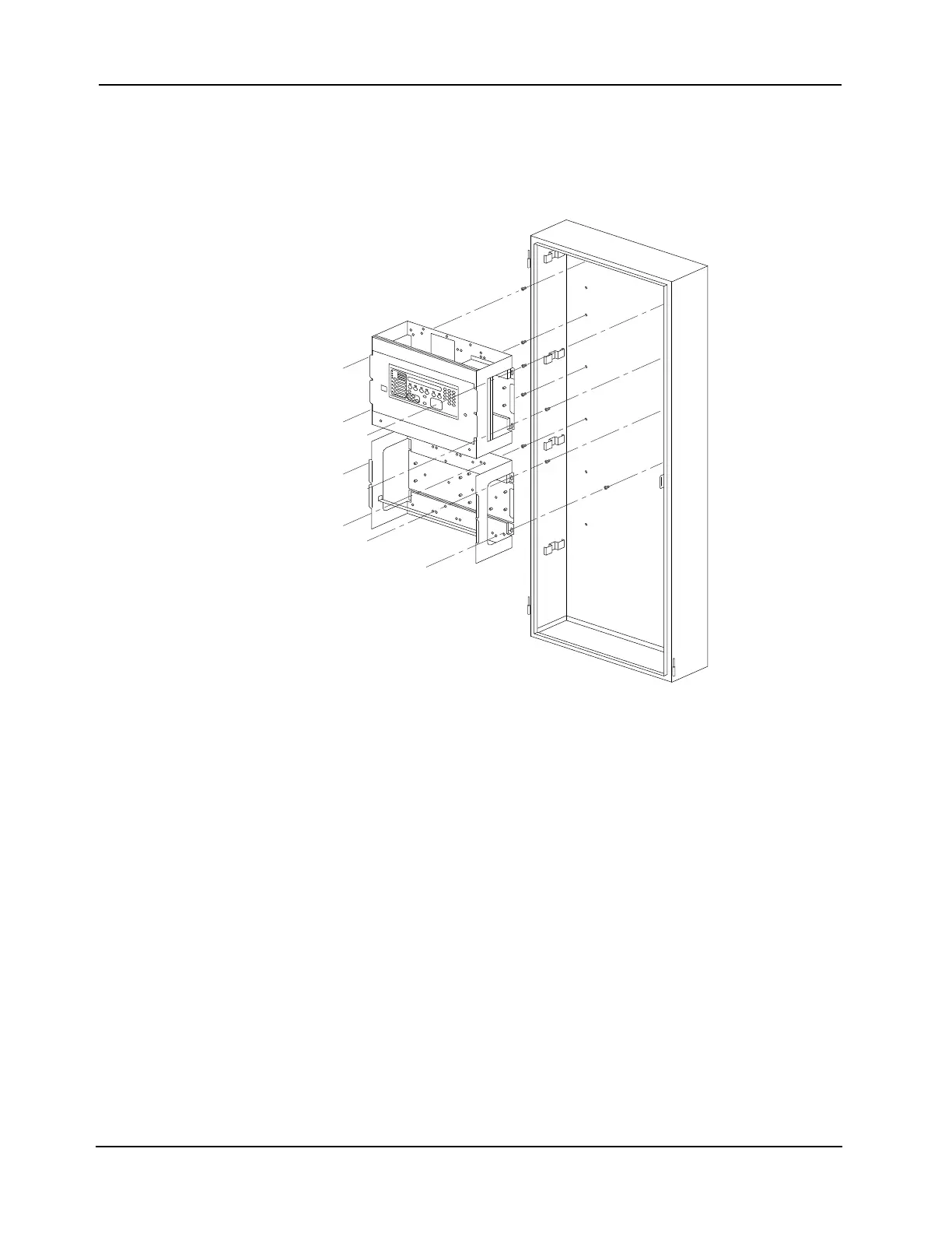
8. Mount the system electronics bay assemblies in the back box by carefully placing the
assembly onto the four extended screws in the back box, allowing the electronics bay
assembly to hang from the screws.
9. Securely tighten all mounting screws. Refer to Table 2-9 for the recommended torque.
Figure 2-18. Installing the System Electronics Bay Assembly
At this point, the system is ready for system card installation. For information on card
installation, refer to the Panels’ installation manual
.
IMPORTANT: Do not apply power to the system at this time.

Table of Contents

Other manuals for Simplex 4100ES

Questions and Answers:

Question and Answer IconNeed help?

Do you have a question about the Simplex 4100ES and is the answer not in the manual?

Simplex 4100ES Specifications

General IconGeneral
TypeFire Alarm Control Panel
DisplayLCD
Battery BackupYes
Model4100ES
ManufacturerSimplex
Communication ProtocolOptional Ethernet
Signaling Line Circuits (SLCs)Up to 10
Notification Appliance Circuits (NACs)Up to 10
Agency ListingsUL, FM, CSFM, MEA
Max Relay Circuits20
Communication PortsEthernet
Operating Temperature32°F to 120°F (0°C to 49°C)
HumidityUp to 93% RH, non-condensing

Related product manuals