10-5
Chapter 10 MNS/ECS Application
Programming and Configuration
Programming the
4100ES to Meet
MNS
Requirements
The programming for an MNS is not special; it can be accomplished using priority, modes, and
Custom Control. Any technician who has attended training and become a certified 4100ES Fire
Alarm Technician should be capable of programming the 4100ES for MNS combined with Fire
Alarm service.
Program a key for the reset of MNS panic switch alarms. The key mode should be type “PBT”,
with the reference address of P216. The adjacent LED should be programmed to track the
status of the reset window timer, illuminating for the duration of the reset cycle. The reset
window timer is A214.
MNS requires that dedicated LEDs be programmed for any MNS-specific service. It is
appropriate to use Priority 2 for MNS alarms. Pri 2 could also be used to indicate another
alarm, such as CO. In a case of multiple Pri 2 alarms, LEDs must be added for each type of
service. Program these LEDs to track the state of the points involved in that service.
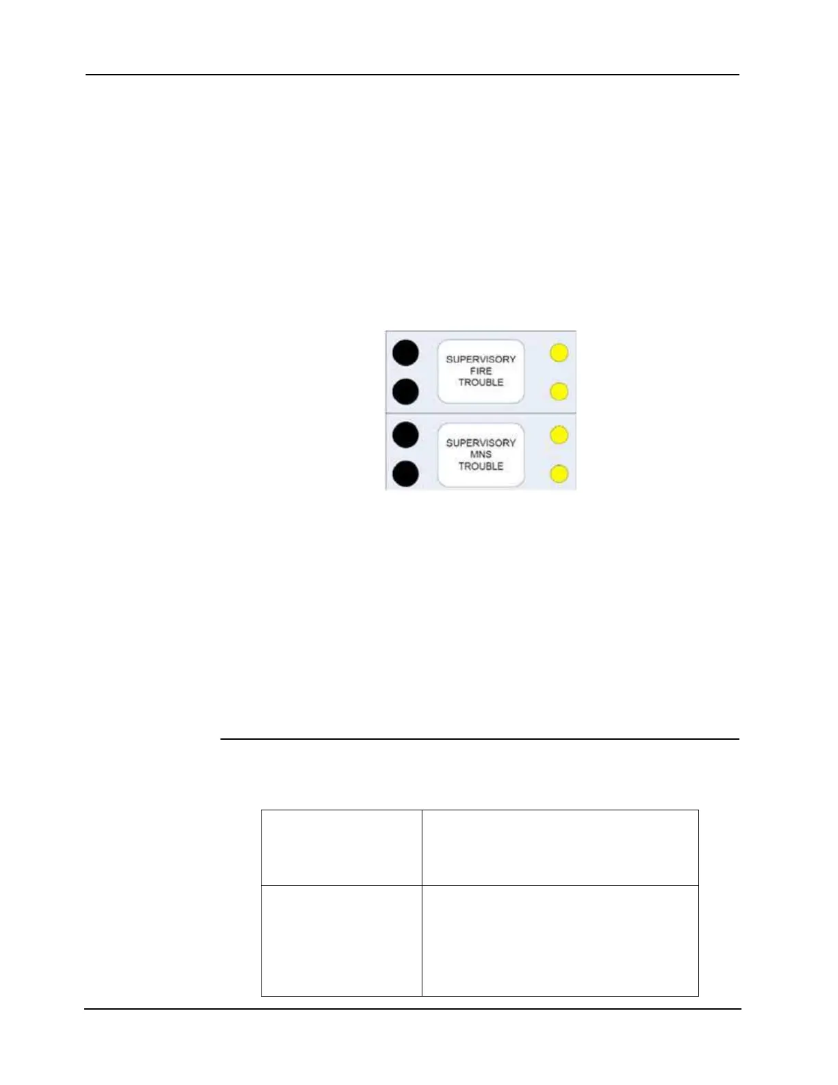
Figure 10-1. Supervisory and Trouble LEDs for both MNS and Fire
MNS can also have Supervisory inputs, which should still be programmed as Supervisory in
order to activate the sounder and the Supervisory indicator. A dedicated LED for each type of
service must also be programmed. For example, a fire supervisory would light a dedicated fire
supervisory LED, as well as the general supervisory LED. An MNS supervisory would light a
dedicated MNS supervisory LED as well as the general supervisory LED. This is to comply
with a UL2572 requirement for an indication of each type of service without activating any
controls.
The same requirement holds when there are MNS specific points. They should light the general
trouble LED and sound the piezo. They should also be programmed such that an LED tracks
the trouble status of MNS points and a separate LED tracks the trouble status of fire alarm
points.
Minimum
Configuration for
LOC and ACU
The minimum configuration for LOC and ACU is listed below.
Table 10-1. Minimum Configuration for LOC and ACU
Controls
•MNS Reset
• MNS Alarm activation
• MNS Take Command/Relinquish Command
•CO Reset
Indicators
• MNS Supervisory LED
• MNS Trouble LED
• CO Alarm LED
• ACU in Control LED
• CCS in Control LED
• LOC in Control LED