B-11
Appendix B
Step 2. Mounting Electronics Bays to Back Boxes (continued)
Installing the
System
Electronics Bays
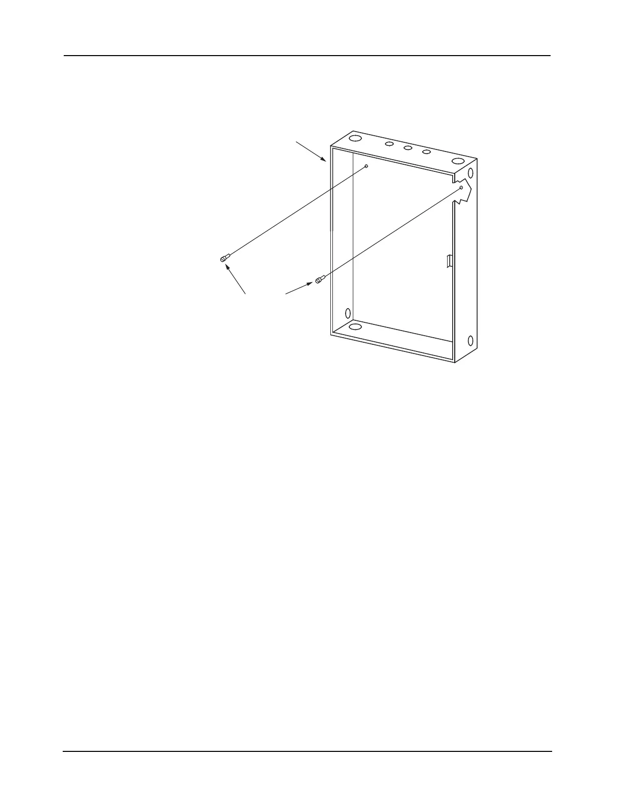
3. Using the hardware provided (as referenced in Table B-2), insert a mounting screw in both
the top right and top left track support holes in the back box as shown in Figure B-13.
Figure B-13. Inserting the Mounting Screws
4. Tighten the two mounting screws, but leave a 1/8-inch (3-mm) gap from the seated position
of each screw.
5. Using the vertical rails as handles, carefully lift the system electronics bay assembly and the
terminal block from the shipping container.
Continued on next page