2-8
Chapter 2 Installing FACP Components
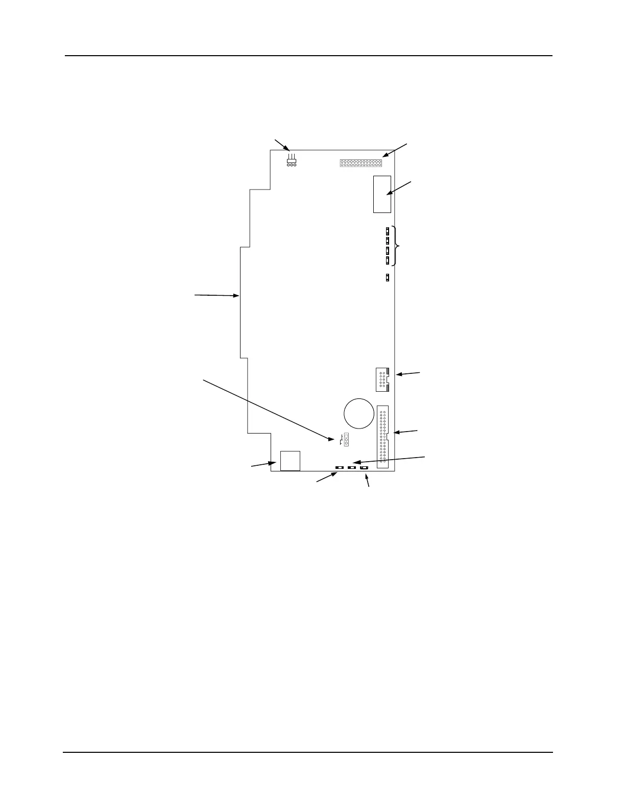
Master Controller
Daughter Card
(566-719)
The master controller daughter card mounts onto the master motherboard. The master
controller daughter card contains a service port, a direct drive user interface connection, and a
port for a service modem.
Figure 2-7. Master Controller Daughter Card (566-719)
MODEM
2
1DEL
2DEL
3DEL
YALPSIDTROP ECIVRES
FFO TABNO TAB
SERVICE MODEM
CONNECTOR (P4)
BATTERY BACKUP
ON/ OFF JUMPER (P3)
SERVICE PORT (P5)
DIRECT-DRIVE
DISPLAY PORT (P6)
NNECTOR TO CPU
MOTHERBOARD (P9)
SERVICE PORT
CPU BOOTLOADER
LEDs (LED A – LED D)
RESET LED (LED1)
ON: CPU is in reset. If LED is flashing,
board is unable to come out of reset.
Possibly corrupt CFIG or board needs
to be replaced.
OFF: CPU is running normally.
RESET (WARM START)
SWITCH (SW1)
Battery
ETHERNET CONNECTOR
(J1) RJ45 TYPE
SWAP CFIG JUMPER (P15)
INSERT JUMPER DURING
BOOT FOR CFIG SWAP
COLD START SWITCH (SW2)
HOLD DURING BOOT FOR
COLD START
COMPACT FLASH
Used for alternative job/
exec storage (card does not “run”
out of compact flash)