8-9
Chapter 8 EPS and IDNet 2 Wiring
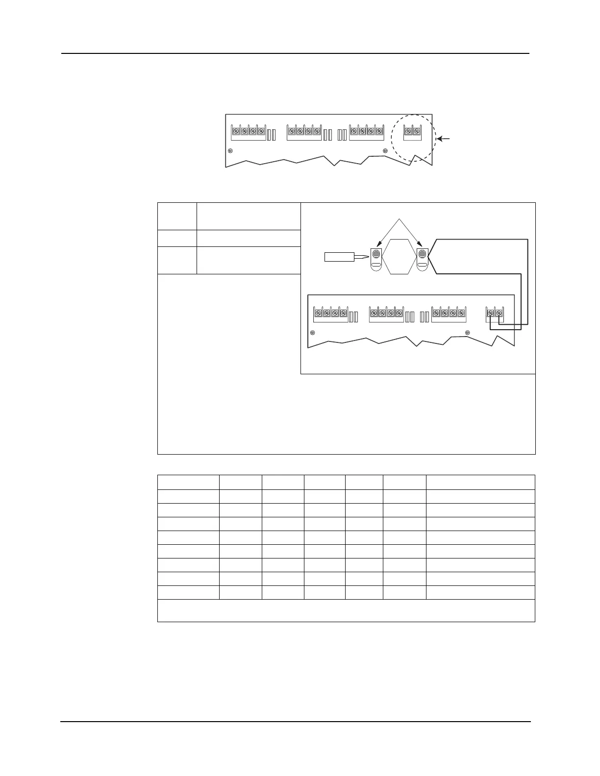
EPS Auxiliary Power Wiring
AUX/ NAC
Terminal
The AUX/NAC terminal block is located on the top right corner of the EPS.
Through the ES Panel Programmer, this point can be configured as either a 24V Auxiliary
(AUX) power or as a simple reverse polarity Notification Appliance Circuit (NAC).
Figure 8-5. AUX/NAC Terminal
Note: Output of AUX or NAC is 24V nominal. Minimum voltage is 19.5 @ full load and minimum battery;
maximum is 31.5V at light load, high AC line. Aux Loads include 4601-9101 Annunciator, 4100-96xx
series Annunciators, 4090 series of IDNet ZAMs and IAMs and any Listed device operating within the
output limits of the AUX. Calculate wiring loss for actual devices used. Compatible Appliances include
4904 series of free-run strobes, 4901 series non-smartsync horns, 4098 series TrueAlarm Sounder
Base, 4090-9005 and -9006 SRP and 4009 NAC extenders, used in reverse-polarity activation mode.
Table 8-5. AUX/NAC Wiring Specification
Voltage
rating:
24V Special Application
Rating: 2 A, maximum
Wiring
gage:
18 AWG (min.)
to 12 AWG (max.)
Wiring Notes:
1. All wiring from the AUX/NAC is
power limited.
2. Conductors must test free of all
grounds and stray voltages before
connection to appliances and panel.
Figure 8-6. Simple NAC Wiring
3. Terminate Class B NACs as shown using 733- 894. For Canadian applications, mount end-of-line resistor to
TEPG-US Model 431537 EOL plate in accordance with ULC-S527.
4. If circuit is terminated with a 10k EOLR, at the terminals, remove this resistor before wiring.
5. If wiring is routed outside the building, use of a listed secondary protector is required. Use Simplex 2081-
9028 or 2081-9044. A protector must be installed at each building exit/entrance. Each 2081-9028 adds
0.2 ohms wiring resistance. 2081-9044 adds 6 ohms wiring resistance, and will greatly reduce wiring
distance.
Table 8-6. NAC Wiring Limits
Alarm Current 20 AWG 18 AWG 16AWG 14 AWG 12 AWG
Line Resistance
(Ohms)
0.25 617 ft 981 ft 1560 ft 2480 ft 3944 ft 14.00
0.50 308 ft 490 ft 780 ft 1240 ft 1972 ft 7.00
0.75 206 ft 327 ft 520 ft 827 ft 1315 ft 4.67
1.00 154 ft 245 ft 390 ft 620 ft 986 ft 3.50
1.25 123 ft 196 ft 312 ft 496 ft 789 ft 2.80
1.50 103 ft 163 ft 260 ft 413 ft 657 ft 2.33
1.75 88 ft 140 ft 223 ft 354 ft 563 ft 2.00
2.00 77 ft 123 ft 195 ft 310 ft 493 ft 1.75
Note: This Chart indicates the maximum distance for 1/4 -2A loads. Wiring distance is from the panel termi-
nals to the last appliance. Use of a 2081-9044 protector reduces wiring distance.
+ + - -
+ + - -
+ + - -
IDNAC1 IDNAC2 IDNAC3
AUX
IDNAC1 IDNAC2 IDNAC3
+AUX-
Auxiliary Power
Terminal Block
733-894
10K EOLR
TYPICAL APPLIANCES
NAC -
NAC+
+ B
- B
+ + - -
+ + - -
+ + - -
IDNAC1 IDNAC2 IDNAC3
+AUX-