B-9
Appendix B
Step 1. Mounting Back Boxes (continued)
Installing the
Back Box(es)
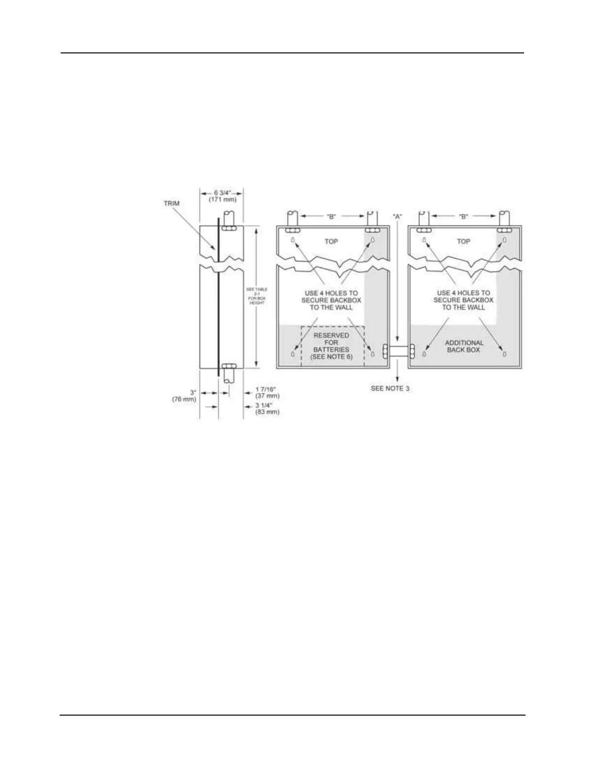
Install the back box as shown in Figure B-11. Use the holes in the back box to secure it to the
wall.
• For mounting to a wooden wall structure, the back box must be attached with
four 1-½-inch-long (38 mm) lag bolts and four ½-inch-diameter (13 mm) washers.
• The enclosure must be level and plumb when installed. The front surface of the back box
must protrude at least three inches from the wall surface for semi-flush back box
installations (refer to Table B-1 and the “Rough Opening” section of the table for semi-
flush installations).
Figure B-11. Back Box Installation Diagram
Figure Notes:Figure B-11 notes:
1. The dimensions shown are typical for all surface and semi-flush installations.
2. Use a suitable punch when conduit is required and no knockout is present.
3. Box mounting:
• Minimum 5 inches from an obstruction on the hinged side of the box to permit at least 90 degree
angle when the door is open.
• Minimum distance of 3 ¼ inches (83 mm) between boxes.
• Maximum distance of 10 inches (254 mm) between boxes.
4. Conduit A denotes internal panel interconnect harnesses and non power-limited wiring.
Conduit B denotes contractor wiring.
5. Do not install any power-limited wiring in the shaded area of the back box as shown in Figure B-11.
This area is reserved for non power-limited devices and circuits (for example, AC power, batteries,
and city circuits). The non power-limited area is determined by the internal barriers, but is always
below and to the right of these barriers. Do not use the upper right, right, or bottom knockouts for
entrance of power-limited wiring.
6. When the two back boxes are mounted side-by-side, remove the hinge and the lock catch on the
second back box (box on the right). Remount the hinges on the right side of the second back box.
Remount the lock catch on the left side of the second box. Mount the door
upside-down so the locks on both boxes are side-by-side.