B-5
Appendix B
Introduction to FACPs (continued)
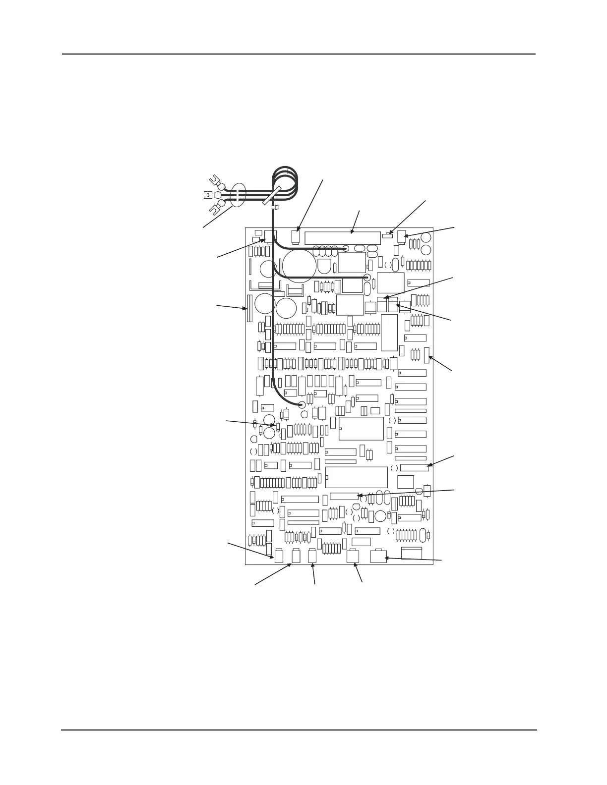
Universal Power
Supply (UPS)
The power supply controller card contains the switches and jumpers for configuring the power
supply, as shown in Figure B-7.
Note: See “Step 3. Configuring Modules,” later in this chapter, for information on configuring switches and
jumpers.
Figure B-7. Universal Power Supply
“B” TAP OUTPUT (P15)
“C” TAP
OUTPUT (P17)
AUDIO
CONTROLLER
INTERFACE (P8)
COMM PORT
(P4)
“A” TAP
RETURN (P1)
“B” TAP
RETURN (P2)
“C” TAP
RETURN (P3)
CURRENT-LIMIT
RESISTOR 2 FOR
“C” TAP CHARGER
ADDRESS
CONFIGURATION
DIP SWITCH (SW2)
UPS
CONFIGURATION
DIP SWITCH (SW1)
PMSI PORT (P5)
BATTERY/NO
BATTERY
JUMPER (P6)
SWITCHER
PORT (P9)
“A” TAP OUTPUT
(P14)
POWER
HARNESS
OUTPUT
CONNECTIONS
EARTH DETECT
JUMPER (P16)
CURRENT-LIMIT
RESISTOR 2 FOR
“B” TAP CHARGER