2-27
Chapter 2 Installing FACP Components
Step 6. Installing Modules into Expansion Bays (continued)
Motherboard
Placement
Guidelines for a
4100ES bay
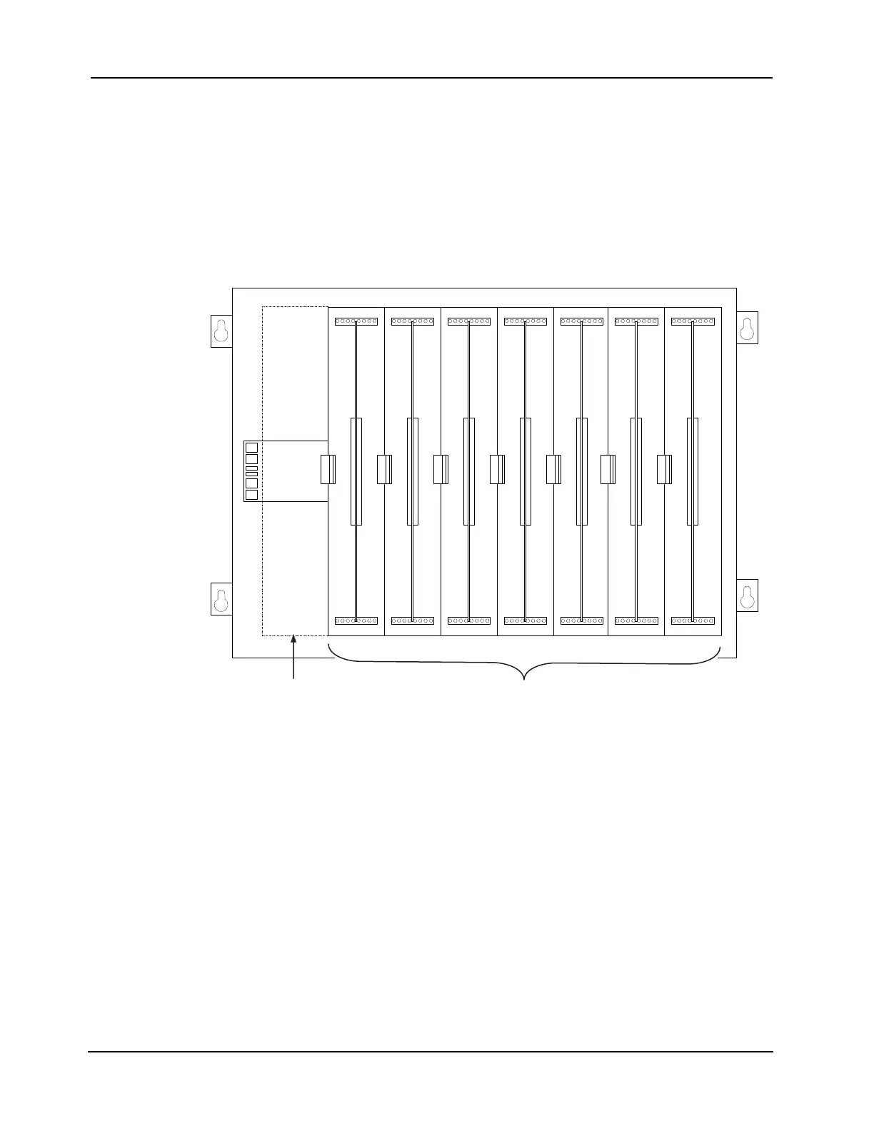
• Motherboards can be installed on top of the PDI in expansion bays. The data and power
that would normally be bussed via the PDI is instead routed across the boards by a
connector from one board to the next.
• Up to eight 2” x 11 ½” motherboards can be installed in an expansion bay if no 4” x 5”
modules are installed in the bay, and if the pins on the left connector (usually P1) on the
leftmost motherboard are removed.
• Motherboards must be added from left to right.
• Relay motherboards must be the rightmost motherboards.
Figure 2-29. Expansion Bay Motherboard Placement
Power Distribution
Interface
dB noitpO 0014
dB noitpO 0014
dB noitpO 0014
dB noitpO 0014
dB noitpO 0014
dB noitpO 0014
dB noi
t
pO 0014
Slot 2 Slot 3 Slot 4 Slot 5 Slot 6 Slot 7 Slot 8Slot 1
This Slot
Must
Remain
Empty
This slot cannot contain a
motherboard unless the pins
on P1 (or leftmost pin
connector) are removed.
Up to eight 2” x 11 ½” motherboards can be mounted in an
expansion bay. Seven motherboards fit into Slots 2 through 8; the
eighth can be added in Slot 1 if its leftpost pins are removed.