2-26
Chapter 2 Installing FACP Components
Step 6. Installing Modules into Expansion Bays
Overview This section contains placement guidelines and physical installation instructions on installing
4” X 5” cards and traditional motherboards into 4100ES electronics bays.
4100ES
Placement
Guidelines
Refer to the following guidelines before mounting 4” X 5” cards and/or motherboards to an
expansion bay.
• Each expansion bay assembly includes a chassis, two end supports, one LED/switch
frame, and a power distribution interface (PDI) board.
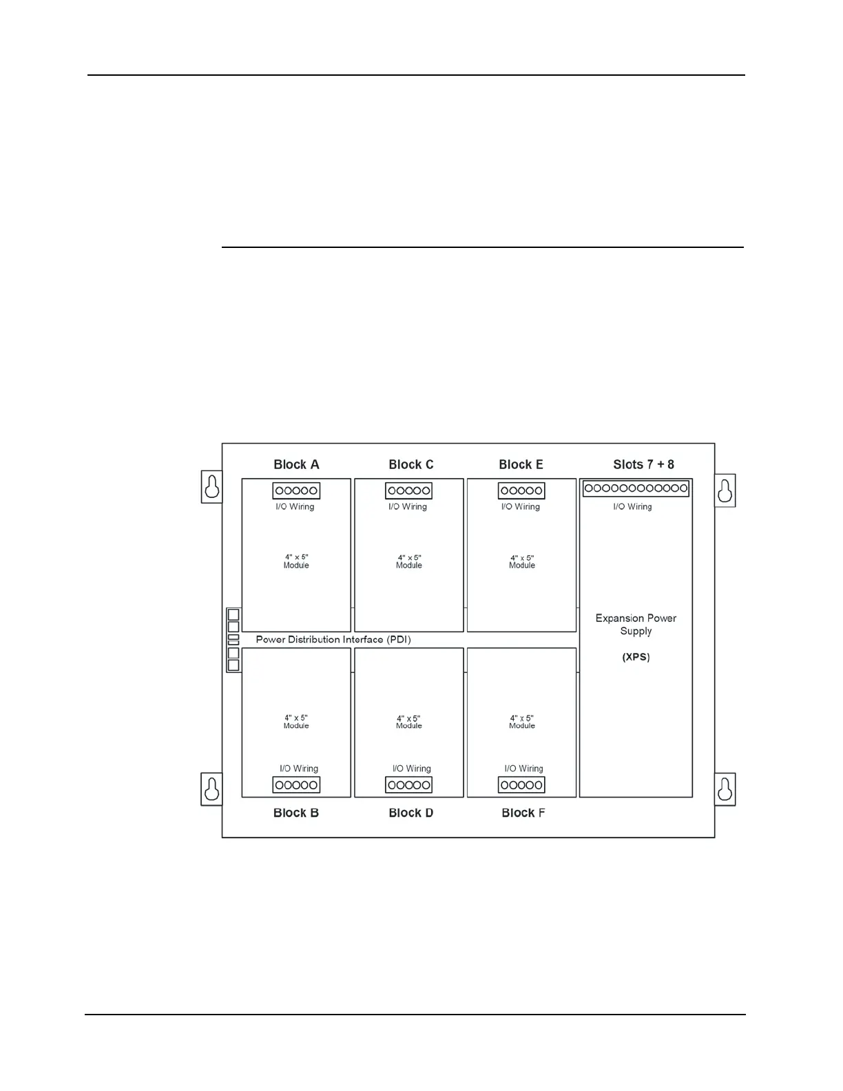
• An expansion bay holds up to eight 4” X 5” modules. A double-size module, such as the
expansion power supply (XPS), takes up two blocks of space as shown below.
• Cards must be added from right to left.
Figure 2-28. Expansion Bay 4” X 5” Card Placement
IMPORTANT: This section applies to aftermarket modules for expansion
bays only. If you do not need to install any aftermarket
modules at all, and if you have followed Steps 1 through 6, you
have completed the panel installation and can apply AC power.