4-4
Chapter 4 Networking
Introduction to the 4100 Network Interface Card (continued)
4100 Motherboard
Options
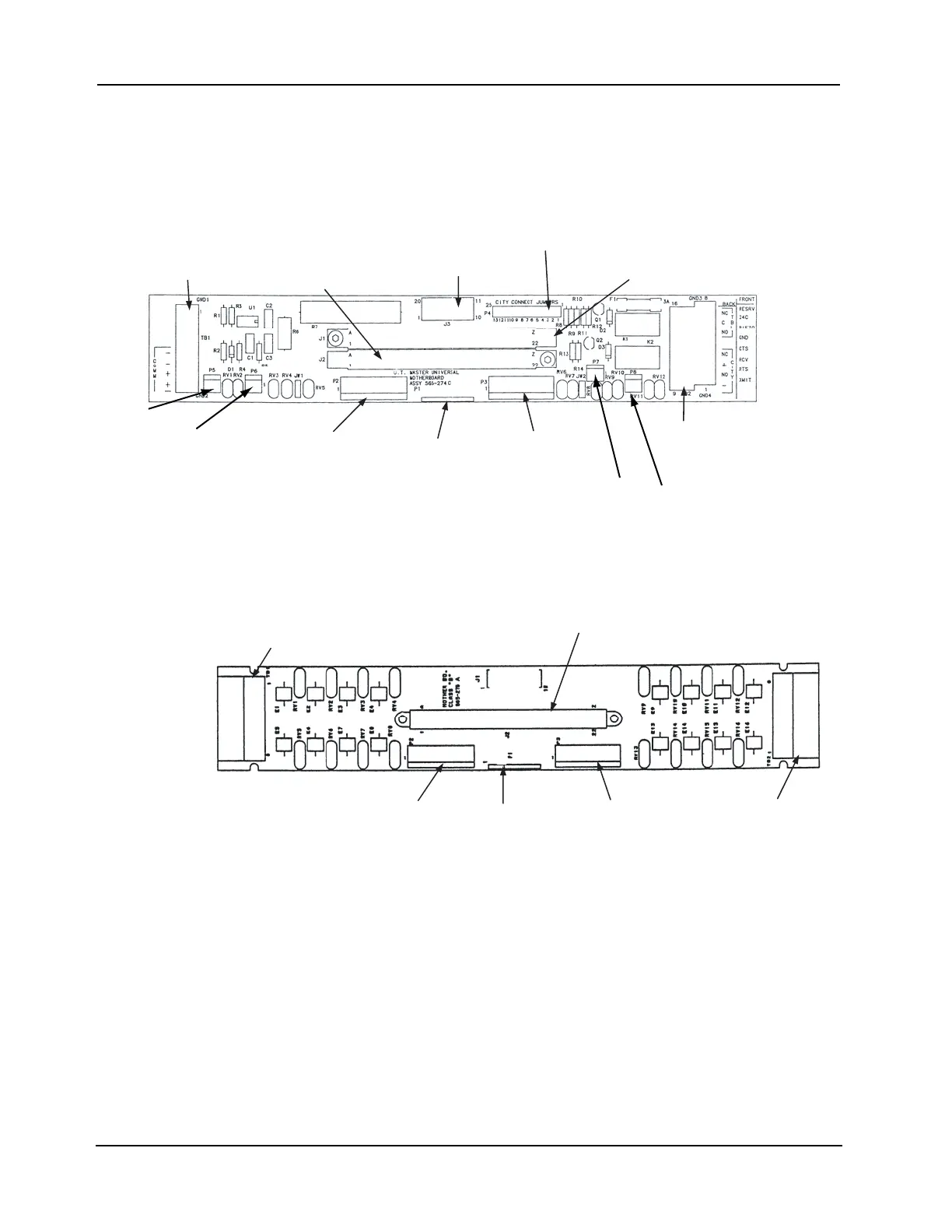
The figures below are illustrations of two motherboards apart from the default CPU
motherboard that can be used with the 4100 NIC.
• The 565-274 Master Motherboard holds two daughter cards: the 4100 master controller
card and the 4100 NIC.
• The 565-275 Class B Motherboard holds the 4100 NIC by itself.
Figure 4-2. UT Motherboard with City Connection (565-274)
Figure 4-3. UT Motherboard without City Connection (565-275)
POWER/COMM BUS
CONNECTOR (J3)
2120 COMM/RS-232 CARD
CONNECTOR (J1)
SYSTEM POWER
CONNECTOR (P3)
INTERNAL COMMS
CONNECTOR (P2)
UT MASTER
CONTROLLER
CONNECTOR (J2)
POWER/COMM BUS
CONNECTOR (P1)
FIELD WIRING
TERMINAL
BLOCK (TB1)
FIELD WIRING
TERMINAL
BLOCK (TB2)
CITY CONNECT
JUMPERS (P4)
P5
P6
P7
P8
SYSTEM POWER
CONNECTOR (P3)
INTERNAL COMMS
CONNECTOR (P2)
POWER/COMM BUS
CONNECTOR (P1)
FIELD WIRING TERMINAL
BLOCK (TB1)
FIELD WIRING
TERMINAL
BLOCK (TB2)
2120 COMM/RS-232 CARD
CONNECTOR (J1)