2-33
Chapter 2 Installing FACP Components
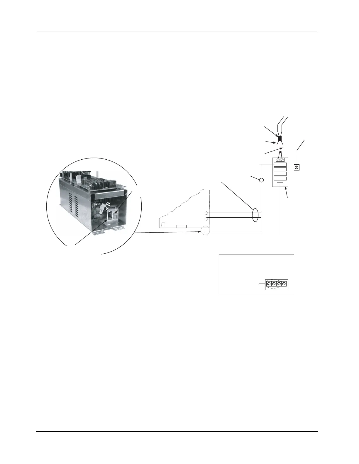
Step 7. Interconnecting Modules and Bays (continued)
Power
Distribution
Module
Connections
5. Connect the 734-012 Harness (734-013 for 220/230/240 V versions) from the next connector
on the PDM to the first XPS or EPS.
• Connect the separate red and black wires (with yellow female terminations) to the battery
plugs on the respective power supplies.
• Connect the white and black wires, which terminate together in a white snap-on connector,
to the connector at the bottom of the power supply assembly, as shown below. The black
wire must be closer to the wall at the power supply connection point.
6. Repeat step 5 for the second power supply, if applicable.
Note: AC wiring is supervised.
Figure 2-35. XPS/PDM Connection
P1
P2
P3
P4
P5
XPS
ASSEMBLY
Bulkhead connector
HARNESS 734-015
TO 24 V BATTERY
RED WIRE
BLACK WIRE
P5
P4
BATTERY
HARNESS
FUSED AT 15 A
GROUND
BACK BOX
GROUND
SCREW
PDM
(566-246)
(or 566-248;
see below)*
HARNESS
(734-012)
(734-013)*
CAV 022
C
AV 032
CAV 042
TUEN
50/60 Hz
2 A
566-248
PDM TERMINAL
BLOCK
Additional bulkhead
connector supplied here
with 220/230/240 V
systems
120 V
NEUTRAL
120 VAC
60 Hz, 4 A
FERRITE
BEAD
*220/230/240 V PART NUMBERS
APPEAR IN ITALICS.