4-21
Chapter 4 Networking
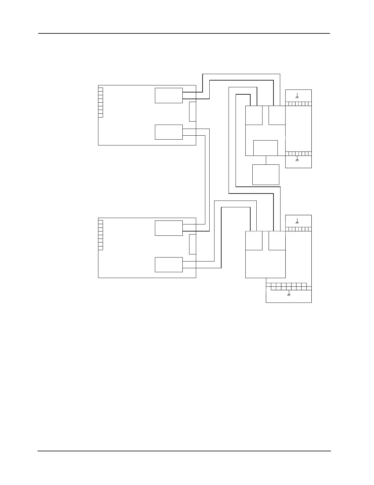
Step 4. Wiring Network Cards (continued)
Modem Media
Wiring (Non-
4100ES/4100U
Only)
Figure Notes:
1. All wiring is 24 AWG twisted pair.
2. Connections between nodes can be made using unpowered (“dry”) copper wires or through powered (“wet”) leased lines.
3. Maximum cable distance between nodes when using short haul is 24 AWG twisted pair is 15,000 feet (4,572 m).
4. Long haul telephone circuits must be private leased lines for analog data, point-to-point, full duplex, two-wire line interface with RJ-11
termination (where no line conditioning or signaling are required).
5. Modem media board power (565-279/566-338): 180 mA. Maximum at 5 +/- 0.25 VDC.
6. Modem media boards operate only at 9600 bps, with an 8-bit protocol.
7. Refer to general wiring precautions in this document, as well as Field Wiring Specifications: document 900-082 for 4100; 900-242 for
4100ES. Refer to Test Specification 576-241 for instructions on how to communicate with the modem.
8. When using a service modem, connect to the 565-516 or 566-793 board using Cable 733-808 in shipping group 740-850. Use Cable
171-095 to connect the modem to a phone jack and/or a telephone termination block. Cut off one end of Cable 171-095 if connecting
to a telephone termination block. Strip back the cable to connect the two center wires to the red and green wires in the block. Refer
to Test Specification 576-241 for instructions on how to communicate with the modem. Place jumpers across 1-2 of P4 and 2-3 of P5.
9. When wiring leaves the building, 2081-9044 Overvoltage Protectors are required. One overvoltage protector is installed where wiring
leaves the building; another is installed where wiring enters the next building.
10. Modem media assemblies have part number 565-279 or 566-338.
11. A network can support can support up to 98 physical bridge nodes. Only four modems are permitted per network.
Figure 4-17. Modem Media Wiring (Non-4100ES/4100U Only)
IMPORTANT: Figure 4-17 applies only to non-4100ES/4100U systems.
0V 2
L -
L +
EARTH
NETWORK
INTERFACE
ASSY
565-518
4020
MODEM
MEDIA
ASSY
LEFT PORT
EARTH
0V 1
R -
R +
TB2
MODEM
MEDIA
ASSY
RIGHT PORT
TB1
0V 2
L -
L +
EARTH
NETWORK
INTERFACE
ASSY
565-518
4020
MODEM
MEDIA
ASSY
LEFT PORT
EARTH
0V 1
R -
R +
TB2
"WIRED"
MEDIA ASSY
565-413
"WIRED"
MEDIA
ASSY
565-413
MODEM
MEDIA
ASSY
MOTHER
BOARD
ASSY
565-275
8
MODEM
MEDIA
ASSY
PHONE JACK
OR
TELEPHONE
TERMINATION
BLOCK
4100
PORT
LEFT RIGHT
NETWORK INTERFACE
ASSY 565-516
RIGHT PORT
TB1
7654
+
R
-
R
TB1
1
V
0
321
12345
L
+
L
-
TB2
0
V
2
678
"WIRED"
MEDIA
ASSY
565-413
"WIRED"
MEDIA
ASSY
565-413
MOTHER
BOARD
ASSY
565-274
8
4100
PORT
LEFT RIGHT
NETWORK INTERFACE
ASSY 565-516
7654
+
R
-
R
TB1
1
V
0
321
9 10111213141516
12345678
L
+
L
-
TB2
0
V
2
OR
566-826
OR
566-826
OR 566-793
OR 566-793