2-25
Chapter 2 Installing FACP Components
Step 5. Installing Motherboards into the CPU Bay
Overview This section contains placement guidelines and physical installation instructions on installing
traditional aftermarket motherboards into the 4100ES CPU bay.
Notes: • If you do not need to install individual motherboards into the CPU bay, but need to install
aftermarket modules into expansion bays, skip to Step 7.
• If you do not need to install any aftermarket modules at all, and if you have followed Steps 1
through 5, you have completed the panel installation and can apply power using the power-up and
power-down procedures.
4100ES CPU Bay
Placement
Guidelines
Refer to the following guidelines before mounting a motherboard into a CPU bay.
• There are eight 2” (51 mm) slots on the CPU bay. Slots 1 and 2 are the only available slots
for aftermarket boards.
• If there are more old style 4100 modules than a CPU bay can accommodate, they should
be placed into the next expansion bay.
• For SPS Configuration only: CPU bays do not include a power distribution interface (PDI)
board, so this bay is reserved for motherboard/daughter card modules only.
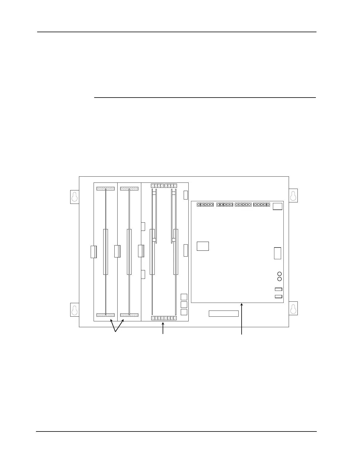
Figure 2-27. CPU Bay Card Placement
CPU Master
Motherboard
2“ Motherboards
Chassis
Power Supply
Slot 1 Slot 2 Slot 3 Slot 4 Slot 5 Slot 6 Slot 7 Slot 8