4-3
Chapter 4 Networking
Introduction to the 4100 Network Interface Card (continued)
Network Module
Illustrations
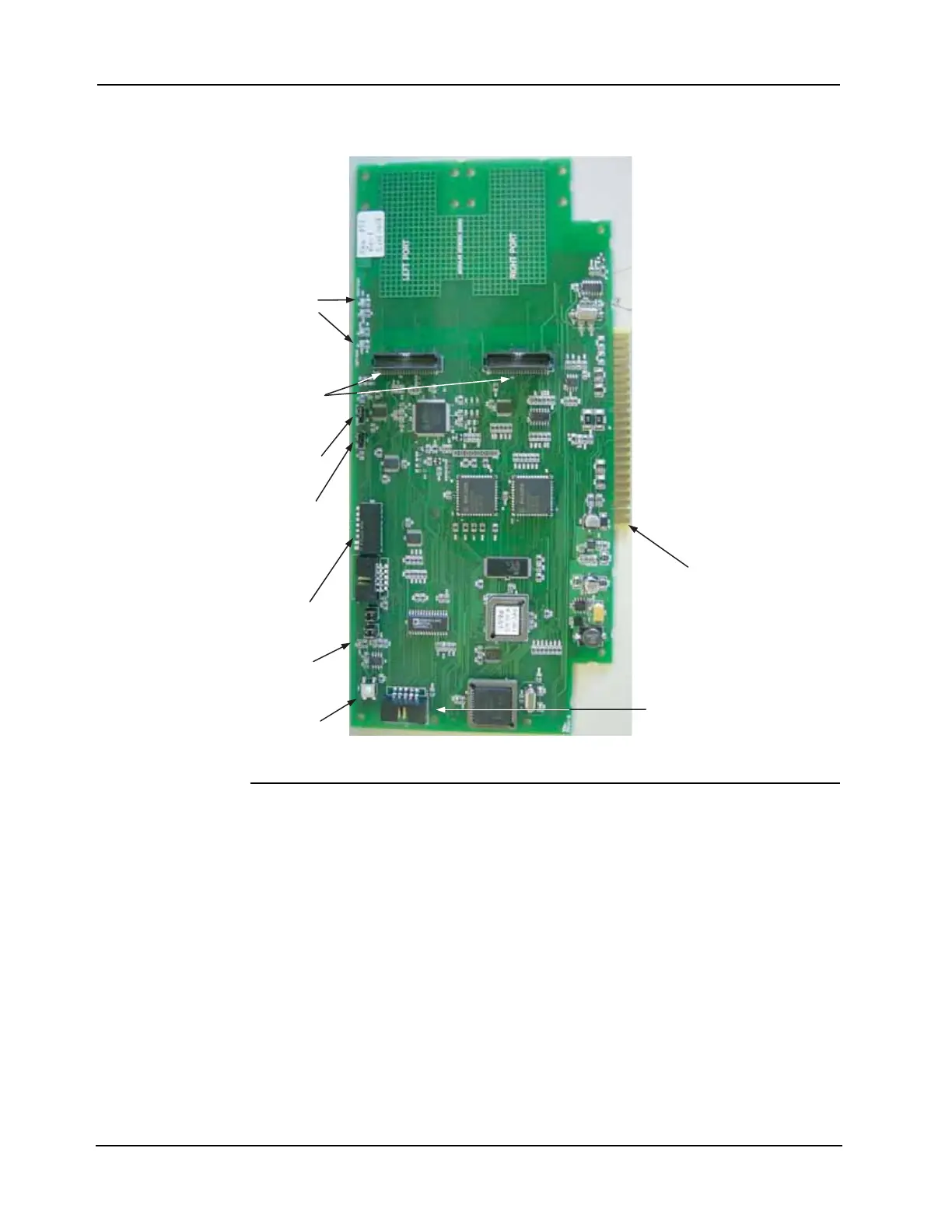
Figure 4-1 depicts the 4100-6014 Network Interface Card.
Figure 4-1. 4100-6014 Network Interface Card
NIC Card LED
Indications
The 4100-6014 NIC has the following LEDs:
LED1 (yellow). Illuminates when
• The host 4100 requests it to illuminate
• A transmission fails
• It is off-line with the 4100 host
• It needs to be configured
LED2 (red). Illuminates when a data ‘0’ is received at the right port.
LED3 (green). Illuminates when a data ‘0’ is transmitted at the right port.
LED4 (red). Illuminates when a data ‘0’ is received at the left port.
LED5 (green). Illuminates when a data ‘0’ is transmitted at the left port.
DATA TRANSMIT/
RECEIVE LEDs
(LED2 THROUGH
LED5)
MEDIA CARD
40-PIN
CONNECTORS
(P5, P6)
DATA RATE JUMPER
PORT (P3)
DATA
PROTOCOL
JUMPER PORT
(P3)
ADDRESS DIP
SWITCH (SW2)
DIAL-UP
SERVICE
MODEM
CONNECTOR
RESET SWITCH
(SW1)
MOTHERBOARD
CONNECTOR (P4)
YELLOW LED
(LED1)