2-2
Chapter 2 Installing FACP Components
Introduction to the FACP
Overview 4100 FACPs are back boxes that contain the CPU, operator interface, FACP power supply, the
power distribution module, the power distribution interface, backup batteries, and any
additional modules that the panel requires.
The FACP is the central hub (often referred to as a host panel) of a standalone or MINIPLEX
fire alarm system. In a networked system, the FACP can be connected to other system FACPs,
so that each host panel is a node on the network.
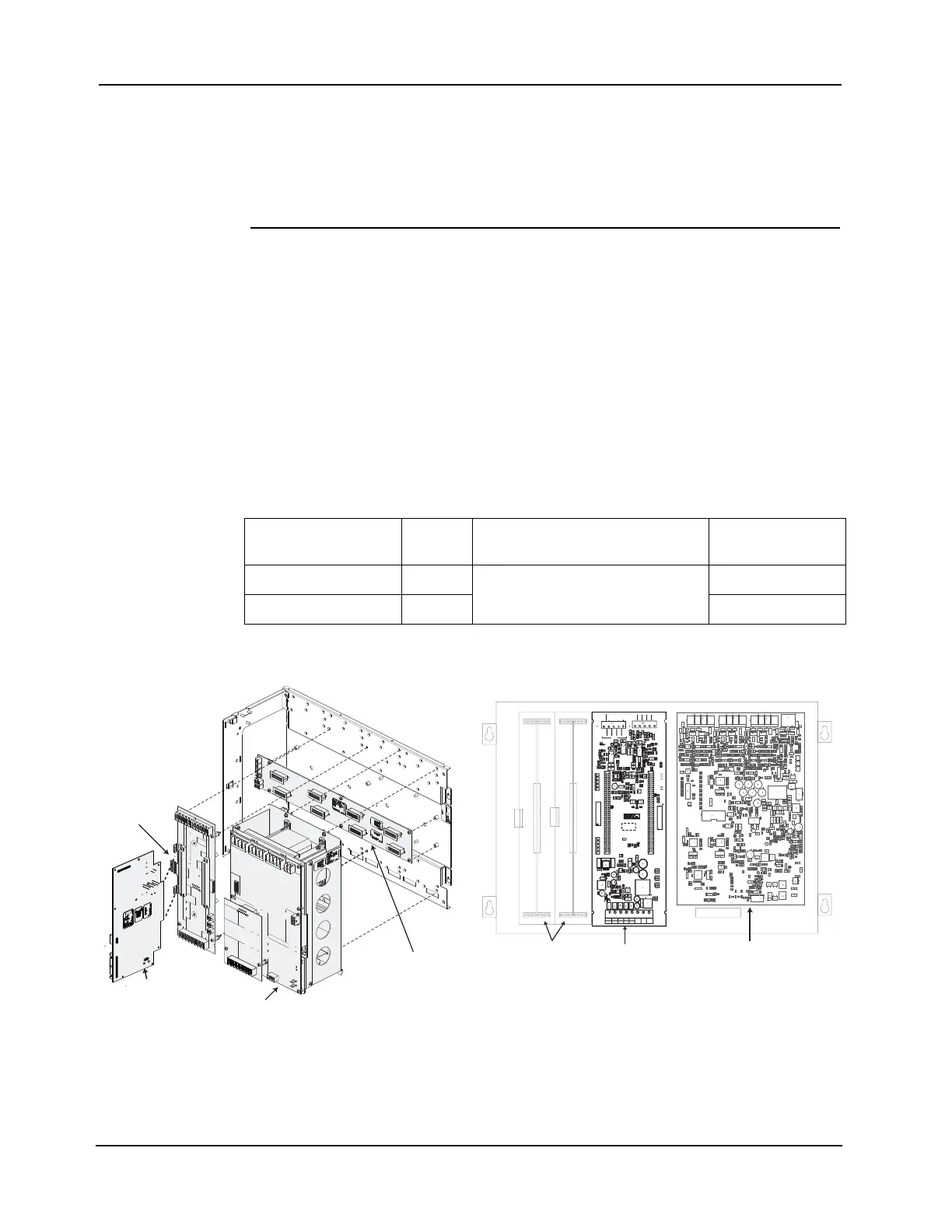
CPU Bay Every FACP contains a CPU bay. The CPU bay is equipped with:
• 1 FACP power supply module.
• 1 RUI+ CPU Master Motherboard:
- In a standalone or MINIPLEX system the CPU motherboard is supplied with a
master controller daughter card attached to it.
- In a networked system a network interface card (NIC) is attached as a second
daughter card to the master motherboard
• 1 Power Distribution Interface (PDI) (EPS configuration only):
- There are eight 2-inch slots on the PDI. Slots 1 and 2 are used for aftermarket
boards. Slots 3 to 8 are taken up by the FACP Power Supply and the CPU Master
Motherboard.
Figure 2-1. The CPU Bay
Table 2-1. CPU Components
Configuration PDI Card Master Motherboard Card
FACP Power
Supply
SPS CPU -
RUI+ CPU Master
Motherboard 566-938
SPS
EPS CPU 8 slots EPS
n o i t u b i r t s i D r e w o P
)
I D P ( e c a f r e t n I
r e t s a M
d r a o b r e h t o M
y l p p u S r e w o P P C A F
d r a o b r e h t o M
l a n o i t p O
s d r a o b r e h t o M “ 2
s i s s a h C
y l p p u S r e w o P
s d r a C d r a o b r e h t o M ” 2 l a n o i t p O h t i w w e i V - t n o r F y a B U P C w e i V - e d i S y a B U P C d e l b m e s s a s i D
IDP
R+
SRVD
R-
ND
0V-
1
RS232
XMIT
GND
RTS
CTS
RCV
1 D E L
2 D E L
3 D E L
RU A I-
RU A I+
RU B I-
RU B I+
Shield
1 troP
6 P
3 2 1
-
L
DVRSR2
-
V
0D
N
G
+
L
DV
R
SRC
4
2OZEI
P
D
N
G
S
TCVCRSTRTI
MX
4 D E L
3 2 1
8 t o l S 7 t o l S 6 t o l S 5 t o l S 4 t o l S 3 t o l S 2 t o l S 1 t o l S
CPU Master
Daughter Card
(EPS Configuration only)
CPU Master
(EPS with IDNet 2
card depicted)
CPU