2-29
Chapter 2 Installing FACP Components
Step 6. Installing Modules into Expansion Bays (continued)
Installing 4 X 5
Cards
The power distribution interface (PDI) is mounted to the back of each expansion cabinet. The
PDI contains slots for up to eight 4 x 5 slave cards. Since the PDI carries power and data across
the entire bay, it solves most interconnection issues, especially between 4 x 5 cards.
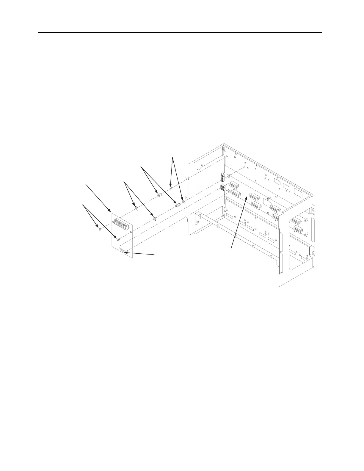
Use the following instructions and Figure 2-31 to mount slave cards to an expansion cabinet.
1. Screw two standoffs and washers to the appropriate holes in the back of the cabinet. These
holes must line up with the screw holes in the card.
2. Plug the card into the appropriate blind mating connector. Seat the card firmly onto the PDI
when installing to ensure complete insertion of the power connector into the PDI.
3. Secure the top of the card to the standoffs with two #6 torx screws and washers.
Figure 2-31. Slave Card/PDI Connection
4” X 5” CARD
STANDOFFS
#6 SCREWS
WASHERS
PDI CONNECTOR
(reverse side)
PDI
SCREW
RETAINERS