B-18
Appendix B
Step 5. Installing Motherboards into Expansion Bays
Overview This section describes how to interconnect motherboards in expansion bays, and how to
connect the expansion bays electrically to the master controller bay.
Guidelines Up to eight 2 (51 mm) x 11 ½-inch (292 mm) motherboards can be installed in an expansion
bay. Adhere to the following guidelines when installing a motherboard in an expansion bay:
• If a power supply is installed, it must be placed on the far right of the bay.
• Relay cards must be installed in the rightmost possible slots (just left of the power supply,
if there is one). This is necessary to allow for the proper routing of non-power limited
wiring (typically 120 VAC wiring), which could be connected to a relay module.
• If a 4100/4120-0155 SDACT or a 4100/4120-0153 CCDACT is installed in the bay, it
must be installed in the far left or far right slot. Neither of these modules contains the J1 or
P1 connectors, which are used to distribute power and communications to adjacent
modules.
Installing
Motherboards
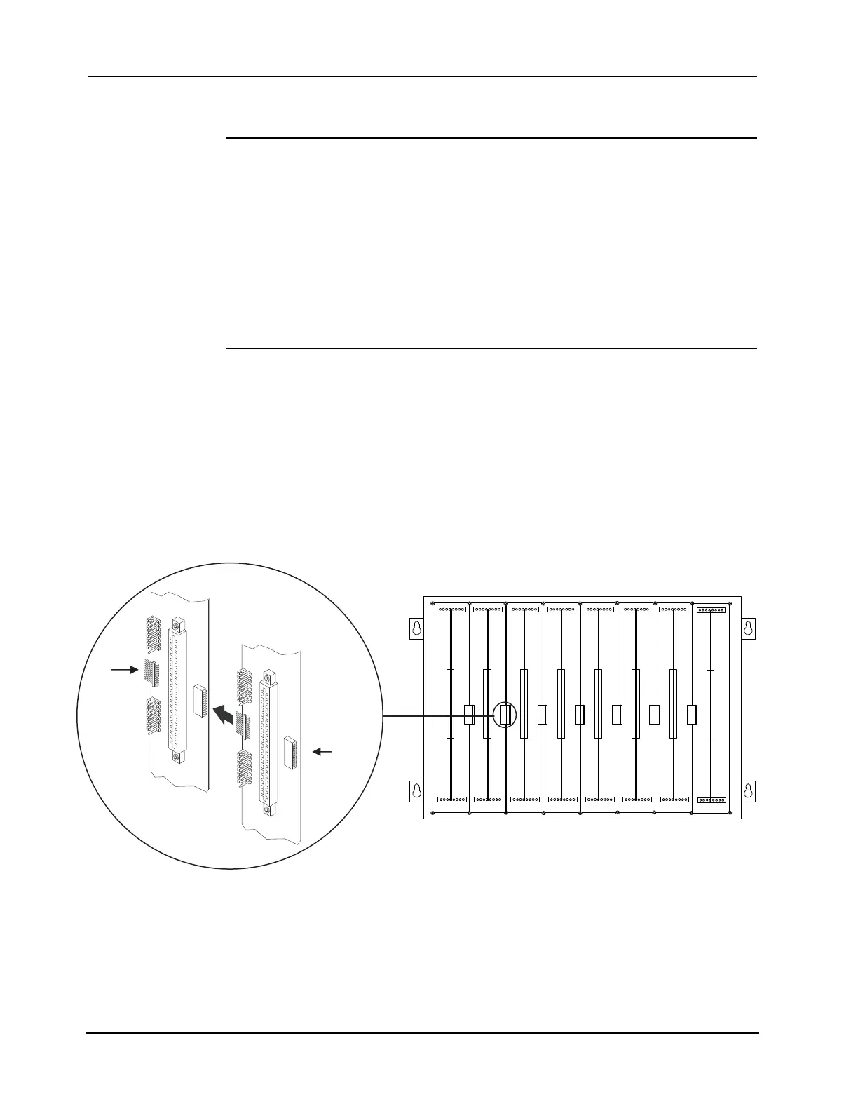
Use the following directions and Figure B-16 to install a motherboard into an expansion bay.
1. Orient the motherboard with the connector labeled J1 on the right and the header labeled P1
on the left.
2. Match the connector on the previously installed motherboard with the pins on the mother-
board you are installing. Slide the motherboard to the left until the pins are completely
inserted in the connector of the previously installed motherboard. If you are installing the
leftmost board, the pins will remain unconnected.
3. Secure the motherboard to the chassis with four torx screws.
Figure B-16. Installing the Motherboard in an Expansion Bay
4. If you are installing the leftmost motherboard, connect a 733-525 Power and
Communication Harness. Continue to the next topic to connect the harness.
The motherboard can be installed in any of the
eight slots.
J1 or
J3
P1