6-10
Chapter 6 4100ES SPS Field Wiring
SPS IDNet Field Wiring Guidelines
IDNet Wiring Up to 250 IDNet initiating devices are supported on the SPS IDNet channel. The SPS supports
both Class A and Class B wiring.
Class A wiring allows IDNet appliances to communicate with the SPS even in the event of a
single open circuit somewhere in the loop. Class A wiring requires that two wires are routed
from the SPS to each IDNet appliance, and then back again to the SPS.
Class B wiring allows “T” tapping, and therefore requires less wiring distance per installation
than Class A. Additionally, Class B wiring does not require end-of-line resistors, because each
IDNet appliance communicates directly to the SPS.
Guidelines Make sure these guidelines are accounted for before installing the cards.
• For Style 4 operation:
- The maximum distance to any device is 2500 feet (762 m) for 126-250 devices, or 4000
feet (1220 m) if 125 or fewer devices are used.
- “T” taps are allowed.
- The maximum total wire allowed is 10,000 feet, or 0.58uF.
- Maximum allowed line-to-line capacitance (“+” to “-” terminals) is 0.58 uF. For
applications with shielded wire, be sure that the total capacitance from line to line plus
the shield to either line is no more than 0.58 uF.
• For Style 6 operation, the maximum loop distance is 2,500 feet (762 m). “T” taps are not
allowed.
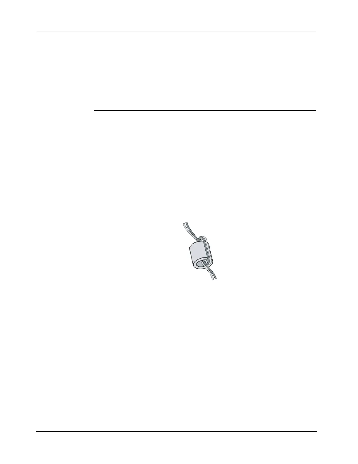
• Use supplied ferrite beads with the SPS. Loop wires once through the supplied ferrite
beads as shown in Figure 6-5.
Figure 6-5. Loop Wiring as Shown