2-7
Chapter 2 Installing FACP Components
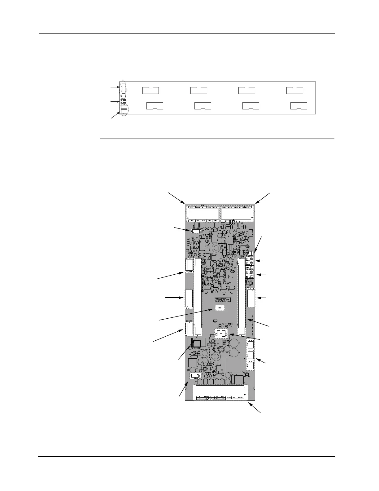
EPS CPU Bay Overview
The Power
Distribution
Interface
In the CPU bay and the expansion bays, power and data are distributed via the PDI. The PDI is
a wiring board with eight card slots, each of which can accommodate a 4 x 5 slave card. If
legacy motherboards are used, they must be mounted above the PDI using metal standoffs.
Note: Power source jumpers P4 and P5 must be placed in position 2-3 (to the right) for proper operation of
an EPS CPU bay.
Figure 2-5. The Power Distribution Interface (PDI)
RUI+ Master
Motherboard
The 4100 Master motherboard has two slots, one is dedicated for the system CPU and The
other slot is typically used for 4120 Network or RS232 cards. The first RUI channel in the
system is the master motherboard. The RUI+ feature on this card provides electrically-isolated
power for the RUI channel, giving it greater immunity to crosstalk from other channels.
The card is installed on the PDI, occupying the space next to the power supply.
Figure 2-6. RUI+ CPU Master Motherboard (566-938)
Note: If the RUI+ Master Motherboard is used to connect to a 4602-6001 (SCU) or 4602-7001 (RCU) move
the P5 and P6 jumpers to the RUI NON ISO position.
4100 POWER DISTRIBUTION INTERFACE
ASSY 566-084
POWER/COMMS
CONNECTORS
(P1-P3)
AUDIO INTERFACE CONNECTORS (P6, P7)
POWER SOURCE
JUMPERS
(P4, P5)
RS-232/Network
Switch
Card Port 2
Network Wired
Media/RS-232
Terminal Block
Power/COMMS to
Adjacent Bay
CPU Slot
10POS female
RUI Earth
Fault LEDs
RUI Trouble LEDs
RUI Terminal
Block
Network Wired
Media/RS-232
Terminal Block
COMM
10POS female
PDI Connector
(on back)
Power
Network/RS232 Slot
RS-232/Network
Switch Card Port 1
Earth Fault
connection to
power supply
(EPS only)
RUI Isolation
Jumpers - See Note
J7
J5
P6
P5
RUI
NON ISO
RUI+
ISO