8-10
Chapter 8 EPS and IDNet 2 Wiring
IDNet 2 Card Wiring
Wiring Overview Each output from the IDNet 2 card can be wired as either an isolated Class A circuit or as two
isolated Class B circuits.
Class A wiring provides an alternate communication path that allows communication to all
devices to be maintained when a single open circuit fault occurs. Class A wiring requires two
wires to be routed from the IDNet 2 Primary Terminals (B+, B-) to each device, and then back
to the IDNet 2 Secondary Terminals (A+, A-). Wiring is in/out, “T” tapping is not allowed.
Class B wiring allows “T” tapping. IDNet 2 wiring is inherently supervised due to individual
device level communications. End-of-line resistors are not required.
Wiring
Parameters
Table 8-7 identifies the IDNet 2 card wiring parameters that must be considered when
installing this card. For additional wiring information see the applicable installation
documentation, or contact your authorized Simplex Product Supplier.
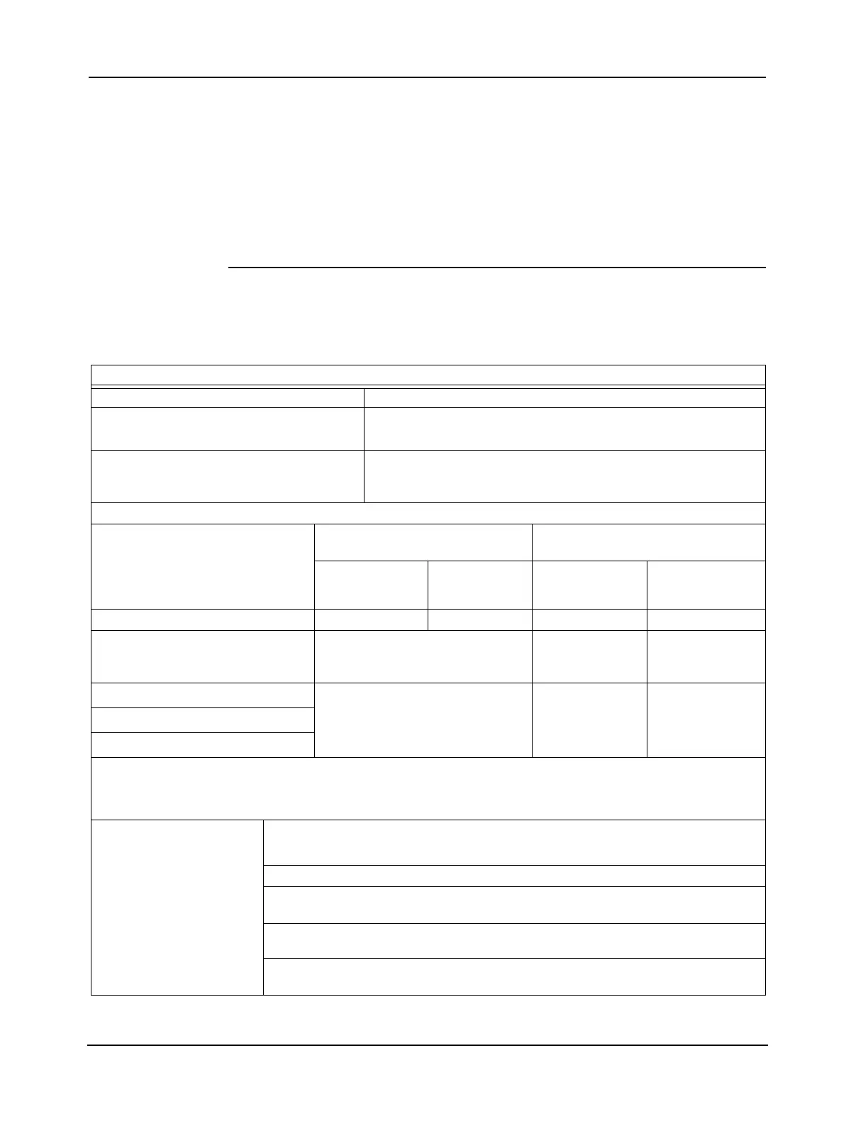
Table 8-7. IDNet 2 Card Wiring Parameters
Wiring Capacitance Parameters
Parameter Value
Maximum Supported Channel Capacitance;
Total of both loops
The sum of line-to-line capacitance, plus the capacitance of either
line-to-shield (if shield is present) = 0.6 µF (600 nF)
Capacitance between IDNet SLCs wiring
(between wires of the same polarity; plus to
plus, minus to minus)
1 µF maximum (this is for multiple IDNet loops)
Wiring Distance Limits (see note below)
Channel Loading Class B Wiring, Total Channel Wir-
ing Parameters, Including T-Taps
Class A Wiring, Total Channel Wiring
Parameters
Up to 125
devices
126 to 250
devices
Up to 125
devices
126 to 250
devices
Total Loop Resistance 50 Ω maximum 35 Ω maximum 50 Ω maximum 35 Ω maximum
18 AWG (0.82 mm
2
)
12 500 ft (3810m) 4000 ft (1219 m)
per loop, 12 500ft
(3810m) total
2500ft (762 m) per
loop, 10 000ft
(3048m) total
16 AWG (1.31 mm
2
)
12 500 ft (3810m)
5000 ft (1524 m)
per loop, 12 500ft
(3810m) total
2500ft (762 m) per
loop, 10 000ft
(3048m) total
14 AWG (2.08 mm
2
)
12 AWG (3.31 mm
2
)
Notes: Maximum wiring distance is determined by either reaching the maximum resistance, the maximum capacitance, or the stated
maximum distance, whichever occurs first. Class A maximum distances are to the farthest device on the loop from either “B” or
“A” terminals. For Class B wiring, the maximum distance to the farthest device is limited to the stated Class A wiring distances.
Shielded wire is not required. Twisted wire is recommended for improved noise immunity.
Wiring Considerations
using 2081-9044
Overvoltage Protectors
(2081-9044 is UL listed to
Standard 1459, Standard
for Telephone Equipment)
Note: External wiring must be shielded (for lightning suppression) and 2081-9044 Overvoltage
Protectors must be installed at building exit and entrance locations.
Capacitance: Each protector adds 0.006 μF across the connected line.
Resistance: Each protector adds 3 Ω per line of series resistance; both IDNet lines are
protected; 6 Ω per protector will be added to total loop resistance.
Maximum distance of a single protected wiring run is 3270 ft (1 km).
Refer to document number 574-832: 2081-9044 Overvoltage Protector Installation
Instructions for additional information.