B-12
Appendix B
Step 2. Mounting Electronics Bays to Back Boxes (continued)
Installing the
System
Electronics Bays
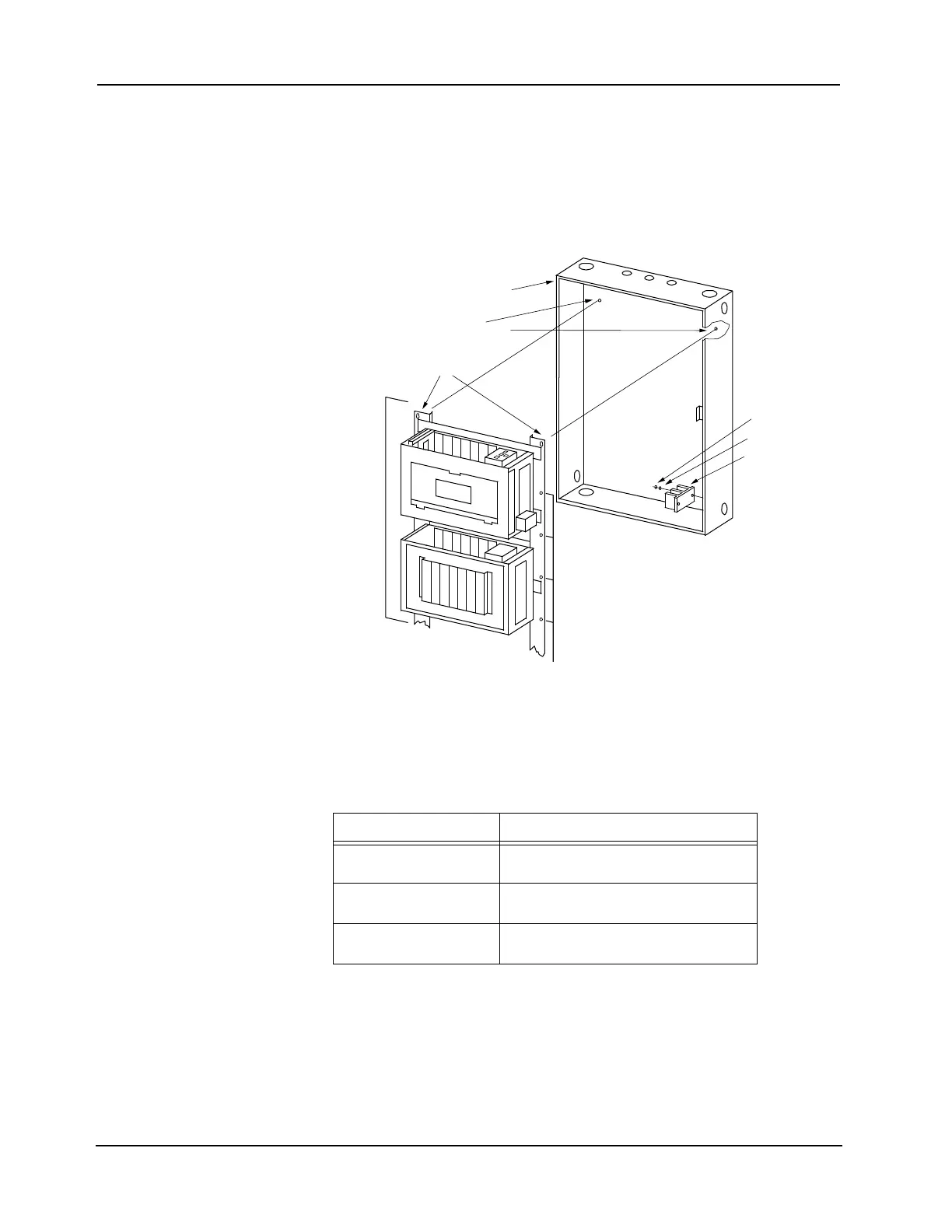
6. Install the system electronics bay assembly in the back box by carefully placing the rail
teardrop holes, located at the top of the rails, onto the two extended screws in the back box,
allowing the electronics bay assembly to hang from the screws. See Figure B-14.
Note: Make sure you do not pinch the terminal block wiring behind the rails as you mount the bay assembly
in the back box.
Figure B-14. Installing the System Electronics Bay Assembly
7. Insert the remaining mounting screws through the screw holes in the rails.
8. Securely tighten all mounting screws. Refer to Table B-3 for the recommended torque.
Continued on next page
Table B-3. Recommended Torque for Mounting Hardware
Screw / Nut Size Recommended Torque
No.6 7.9 to 8.7 inch/ounces
(569 to 626 cm/grams)
No.8 16.1 to 17.8 inch/ounces
(1,159 to 1,282 cm/grams)
No.10 26.8 to 29.7 inch/ounces
(1,930 to 2,139 cm/grams)
TEARDROP HOLES
SYSTEM ELECTRONICS
BAY ASSEMBLY
BACK BOX
TERMINAL
BLOCK
LOCKWASHER
NUT
SCREW HOLES
PREMOUNTED SCREWS