B-3
Appendix B
Introduction to FACPs (continued)
Master
Motherboards
and Controllers
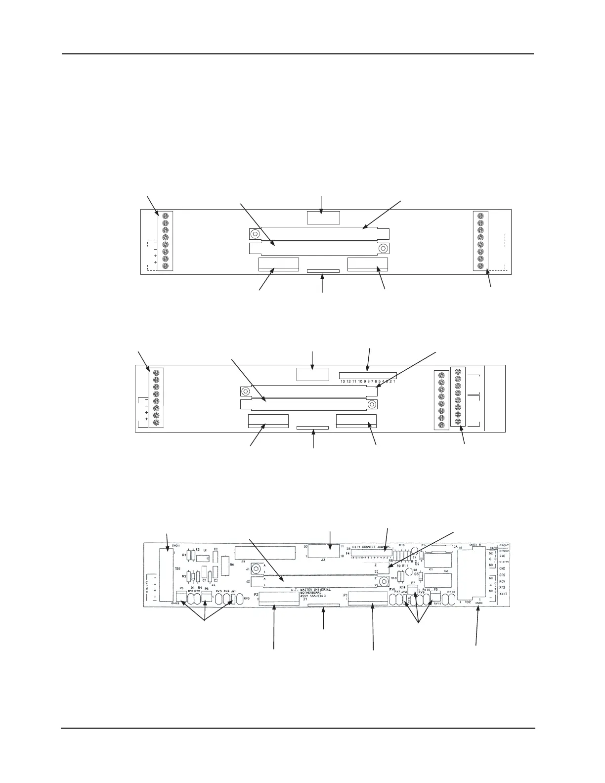
The 4100 master motherboard and controller is the central memory and control point for the
4100 system. It mounts in the leftmost side of the master controller bay.
The figures below are illustrations of the three types of master controller motherboards. They
are commonly referred to as Universal Transponder (UT) motherboards, because they can be
used across different types of older Simplex fire alarm systems.
Note: See “Step 3. Configuring Modules,” later in this chapter, for information on configuring switches and
jumpers.
Figure B-2. UT Motherboard (565-161)
Figure B-3. UT Motherboard with City Connection (565-213)
Figure B-4. UT Motherboard with City Connection (565-274)
Continued on next page
MMOC
1BT
1
1
1J
2P
1P
RESRV
24C
PIEZO
GND
CTS
RCV
1TROP
RTS
XMIT
3P
POWER/COMM BUS
CONNECTOR (J1)
2120 COMM/RS-232
CARD CONNECTOR (J2)
SYSTEM POWER
CONNECTOR (P3)
INTERNAL COMMS
CONNECTOR (P2)
UT MASTER
CONTROLLER
CONNECTOR (J3)
POWER/COMM BUS
CONNECTOR (P1)
FIELD WIRING
TERMINAL BLOCK (TB1)
FIELD WIRING
TERMINAL
BLOCK (TB2)
M
MO
C
TB1
P5
1
J1
P4
GND4
GND3
CITY CONNECT JUMPERS
P2
P1
RESRV
FRONT
24C
PIEZO
NC
BACK
C
NO
NC
+
NO
-
GND
CTS
RCV
RTS
XMIT
P3
P6
JW1 JW1
P8
P7
T
B
L
C
I
T
Y
POWER/COMM BUS
CONNECTOR (J3)
2120 COMM/RS-232 CARD
CONNECTOR (J1)
SYSTEM POWER
CONNECTOR (P3)
INTERNAL COMMS
CONNECTOR (P2)
UT MASTER
CONTROLLER
CONNECTOR (J2)
POWER/COMM BUS
CONNECTOR (P1)
FIELD WIRING
TERMINAL BLOCK (TB1)
FIELD WIRING
TERMINAL
BLOCK (TB2)
CITY CONNECT
JUMPERS (P4)
JW2
POWER/COMM BUS
CONNECTOR (J3)
2120 COMM/RS-232 CARD
CONNECTOR (J1)
SYSTEM POWER
CONNECTOR (P3)
INTERNAL COMMS
CONNECTOR (P2)
UT MASTER
CONTROLLER
CONNECTOR (J2)
POWER/COMM BUS
CONNECTOR (P1)
FIELD WIRING
TERMINAL
BLOCK (TB1)
FIELD WIRING
TERMINAL
BLOCK (TB2)
CITY CONNECT
JUMPERS (P4)
RS-232 / NETWORK
JUMPERS (P5, P6, JW1)
RS-232 / NETWORK
JUMPERS (P7, P8, JW2)
)
U
0
0
1
4-no
N
(