1-7
Chapter 1 Introduction to the 4100ES Fire Alarm System
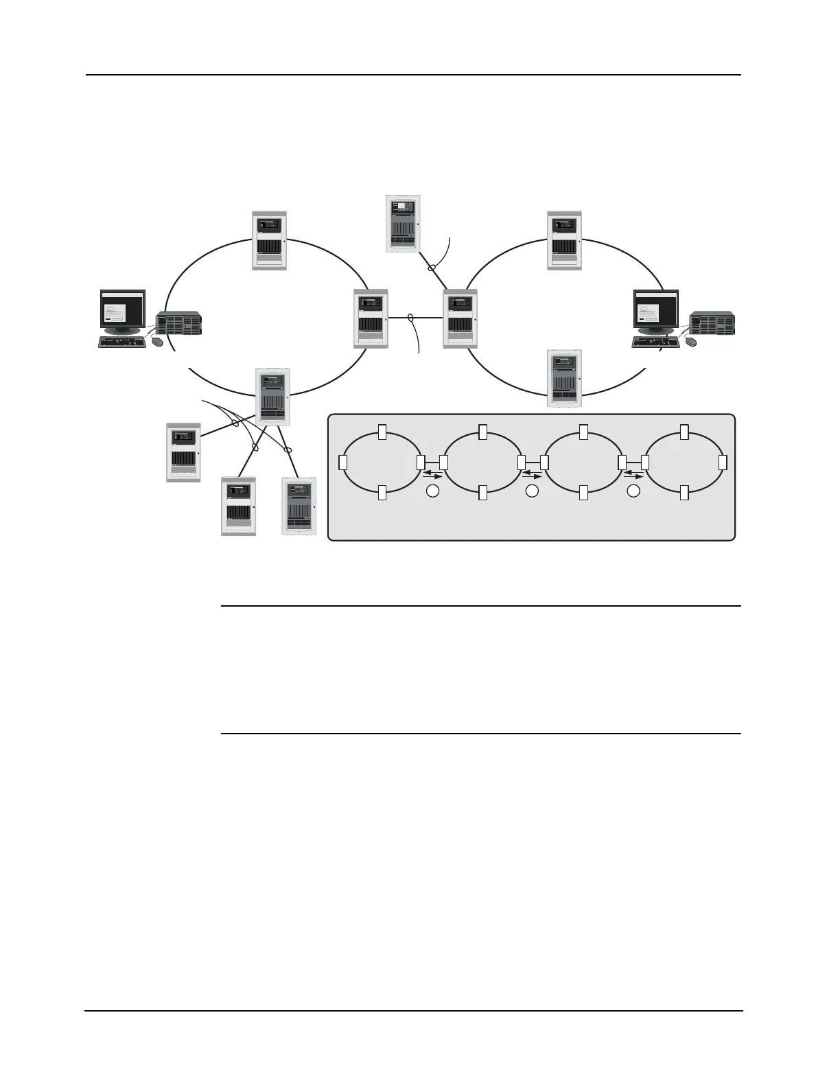
Network configuration (continued)
Connection loops Network loops can be joined via physical bridge cards. There may be no more than two Style 7
network loops (two hub configurations) connected in tandem. For every two loops that are
interconnected (using one physical bridge), there can be a maximum of three physical bridges
used in a star configuration. See Figure 1-4.
Figure 1-4. Interconnected loop configuration
System design To be used as a network node, a 4100ES panel must contain the following:
•CPU
• System Power Supply
• 4100 Network Interface Card
• Optional slave cards
Network
communication
Network communication is achieved via the 4100-6014 Network Interface Card (NIC). Each
network node requires a NIC. Once the FACP is a network node, it may be programmed to be
fully in control of other nodes, or to be fully passive, or anywhere in between.
Overview
This section lists all back box PIDS for the 4100ES Fire Alarm System.
Remote Loop
Physical Bridge Link
Local Loop
Physical Bridging
(Star Configuration)
TrueSite Workstation
Physical Bridge Link
Physical Bridge Links
Hub Node
Hub
Node
Remote Node
Fire Control
Fire Control
TrueSite Workstation
Fire Control
Fire Control Fire Control
Fire Control
1 2 3
Up to Four Network Loops can be
connected using 3 Physical Bridges
Loop 1 Loop 2 Loop 3 Loop 4