B-4
Appendix B
Introduction to FACPs (continued)
Master
Motherboards
and Controllers
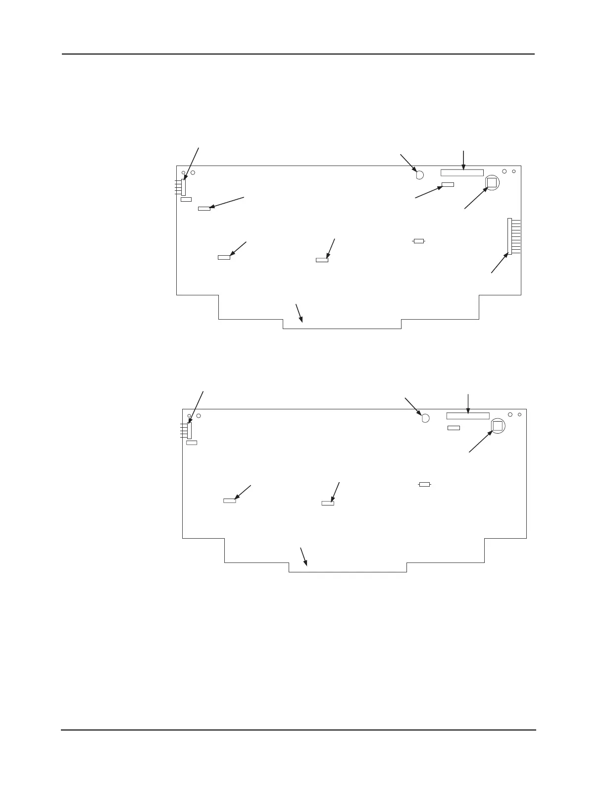
The figures below are illustrations of the two UT master controllers.
Note: See “Step 3. Configuring Modules,” later in this chapter, for information on configuring switches and
jumpers.
Figure B-5. UT Master Controller (565-333)
Figure B-6. UT Master Controller (565-148)
LED1
P6
P7
P5
P3
P2
P1
MODEM
UT MASTER
CONTROLLER
565-333 H
P4
SW1
1
2
PROGRAMMER PORT (P1)
MODEM JUMPER (P2)
BATTERY BACKUP
JUMPER (P3)
FLASH EPROM
JUMPER (P5)
EDGE CONNECTOR TO
565-161 MOTHERBOARD (P4)
SYSTEM TROUBLE
LED (LED1)
MASTER DISPLAY
PORT (P6)
RESET BUTTON
(SW1)
Not used (P8)
MASTER DISPLAY
JUMPER (P7)
LED1
P6
P7
P5
P3
P2
P1
MODEM
UT MASTER
CONTROLLER
565-333 H
P4
SW1
1
2
PROGRAMMER PORT (P1)
BATTERY BACKUP
JUMPER (P2)
FLASH EPROM
JUMPER (P3)
EDGE CONNECTOR TO
565-161 MOTHERBOARD (P5, P6))
SYSTEM TROUBLE
LED (LED1)
MASTER DISPLAY
PORT (P4)
RESET BUTTON
(SW1)