STC8A8K64D4 Series Manual
-
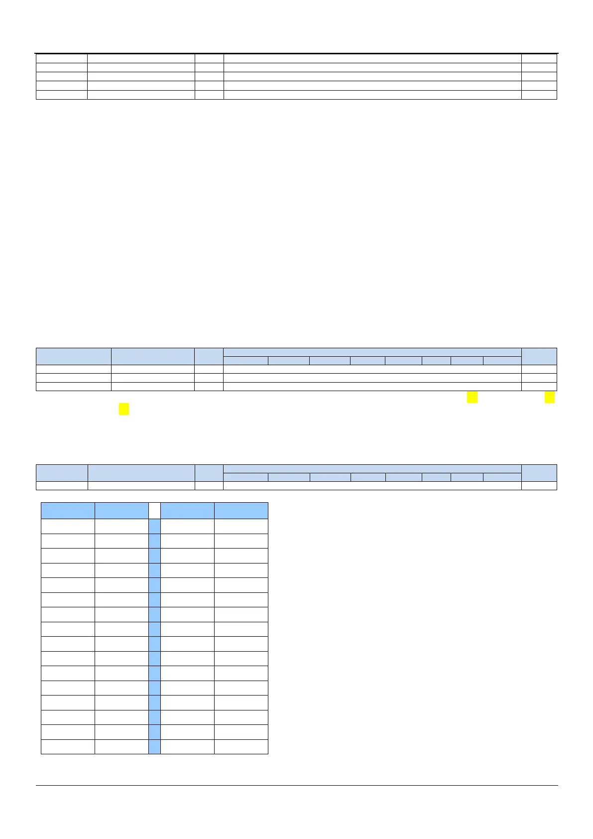
IRC parameter of 45MHz(44M band)
VRTRIM parameter of 6M band
VRTRIM parameter of 10M band
VRTRIM parameter of 27M band
VRTRIM parameter of 44M band
In the STC8A8K64D4 series MCUs, the integrated high-precision IRC is divided into 4 frequency bands, and the reference
voltage value corresponding to every frequency band has been calibrated at the factory. When selecting different
frequency bands, you only need to fill the calibrated voltage value of the corresponding frequency band in the VRTRIM
register. The center frequencies of the 4 frequency bands are 6MHz, 10MHz, 27MHz and 44MHz respectively. Due to
manufacturing errors, the center frequency may generally have a deviation of ±5%. In order to obtain accurate user
frequencies, IRTRIM can be used to fine-tune the frequency. When using the download software provided by STC to
download the user program, the system will automatically set the VRTRIM and IRTRIM registers according to the
frequency set by the user. At the same time, the IRTRIM value of 10 common frequencies and the calibration value of
the reference voltage value of 4 frequency bands are preset in CHIPID, so that the user can dynamically modify the
working frequency during the running of the program.
[CHIPID11 : CHIPID20]: the IRTRIM value of 10 common frequencies. The annotations in parentheses are the corresponding
frequency bands.
[CHIPID21 : CHIPID24]: the calibration value of the reference voltage value of 4 frequency bands.
When the user modifies the frequency dynamically, he only needs to read out a certain frequency calibration value in
[CHIPID11 : CHIPID20] and write it into the IRTRIM register, and at the same time, according to the frequency band
corresponding to the frequency, set a certain voltage calibration value in [CHIPID21 : CHIPID24] Just read and write to
the VRTRIM register. For detailed operations, please refer to the sample programs in the following chapters.
7.4.5 Interpretation of test time parameters in CHIP
The year, month, and day parameters of the test time are all BCD codes. For example, CHIPID27=0x21, CHIPID28=0x11,
CHIPID29=0x18, then the production test date of the target chip is November 18, 2021.
7.4.6 Interpretation of chip package form number in CHIP