STC8A8K64D4 Series Manual
-
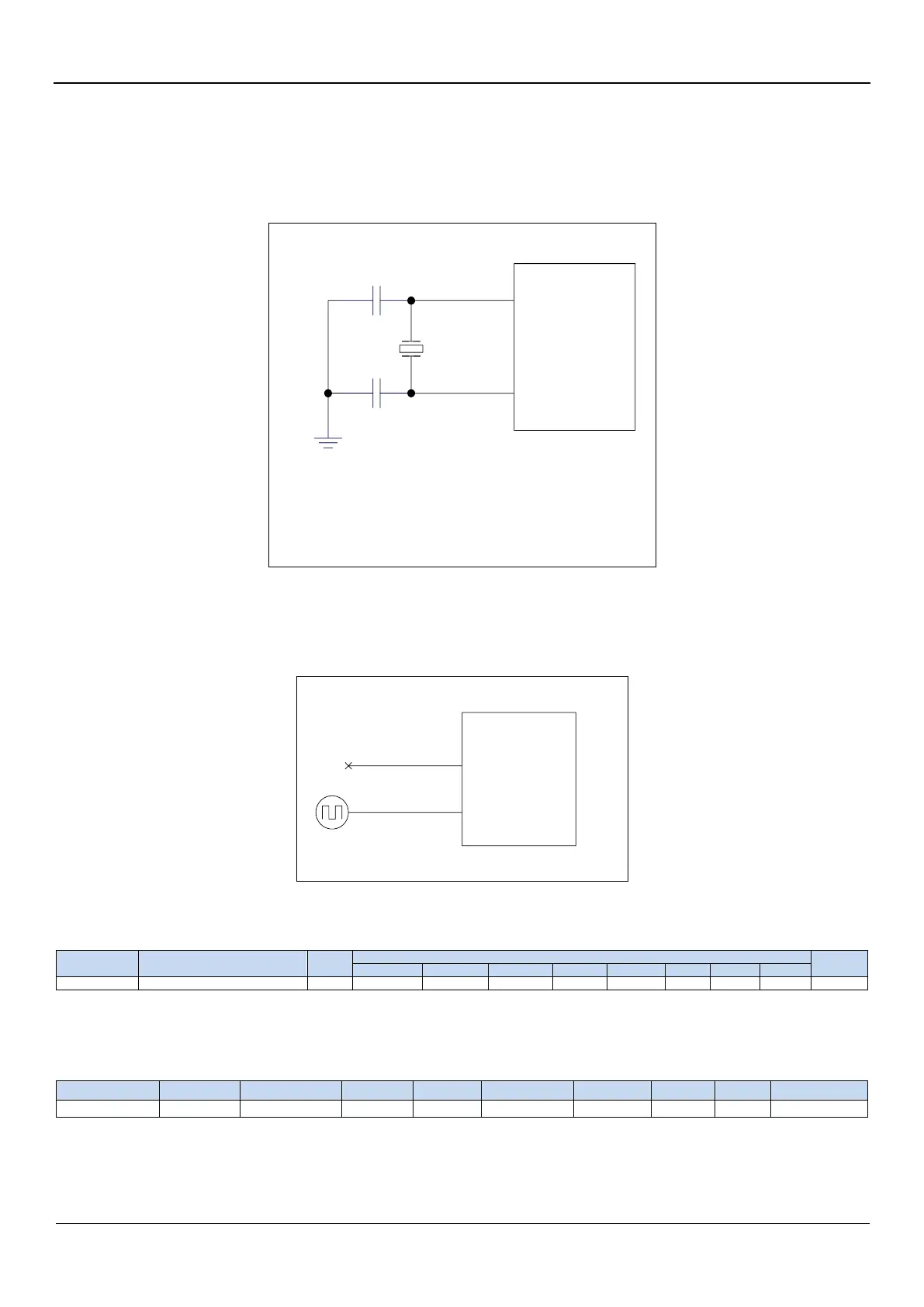
6.4 External crystal oscillator and external clock circuit
6.4.1 External crystal input circuit
P1.6/XTALO
4~45MHz
C1
20p~47p
P1.7/XTALI
20p~47p
C2
MCU
Note: The two capacitors C1 and C2 must not be
omitted. Without these two capacitors, the crystal
oscillator may not oscillate. In addition, even if the
crystal oscillator can start to oscillate, the MCU will
increase the power consumption of 5~8mA.
6.4.2 External clock input circuit (P1.6 cannot be used as general I/O)
P1.6/XTALO
P1.7/XTALI
4~45MHz
MCU
6.5 Clock stop / Power Saving Mode and System Power Management
6.5.1 Power control register (PCON)
LVDF: Low voltage detection flag. When the system detects a low-voltage event, it is set by the hardware automatically and
an interrupt request to the CPU ocuurs. It should be cleared by user software.
POF: Power-On reset flag. It is set by the hardware automatically when power-off-on action occurs.
PD: Clock stop mode / Power-Down mode / Power stop mode control bit
0: No operation.