13.2.9 Timer 1 mode 2 (8-bit auto-reloadable mode)
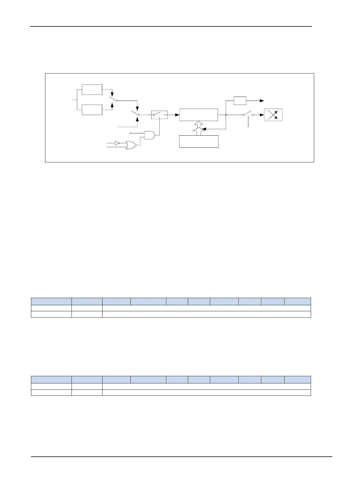
In this mode, Timer/Counter 1 is an 8-bit counter that can be automatically reloaded, as shown in the figure below.
Timer/counter 1 mode 2: 8-bit auto-reloadable mode
The overflow of TL1 not only sets TF1, but also reloads the content of TH1 into TL1. The content of TH1 is preset
by software, and its content remains unchanged during reloading.
When T1CLKO/INT_CLKO.1=1, the P3.4/T0 pin is configured as timer 1's clock output T1CLKO. The output
clock frequency is T1 overflow rate/2.
If C/T=0, the timer/counter 1 counts the internal system clock, then:
if T1 works in 1T mode (AUXR.6/T1x12=1), the output clock frequency = (SYSclk)/(256-TH1)/2
if T1 works in 12T mode (AUXR.6/T1x12=0), the output clock frequency = (SYSclk)/12/(256-TH1)/2
If C/T=1, the timer/counter T1 counts the external pulse input (P3.5/T1), then:
Output clock frequency = (T1_Pin_CLK) / (256-TH1)/2
13.2.10 Timer 0 Counting Registers
When T0 is operating in 16-bit mode (Mode 0, Mode 1, Mode 3), TL0 and TH0 combine into a 16-bit register with
TL0 as the low byte and TH0 as the high byte. For 8-bit mode (mode 2), TL0 and TH0 are two independent 8-
bit registers.
13.2.11 Timer 1 Counting Registers
When T1 is operating in 16-bit mode (Mode 0, Mode 1, Mode 3), TL1 and TH1 combine into a 16-bit register with
TL1 as the low byte and TH1 as the high byte. For 8-bit mode (mode 2), TL1 and TH1 are two independent 8-
bit registers.