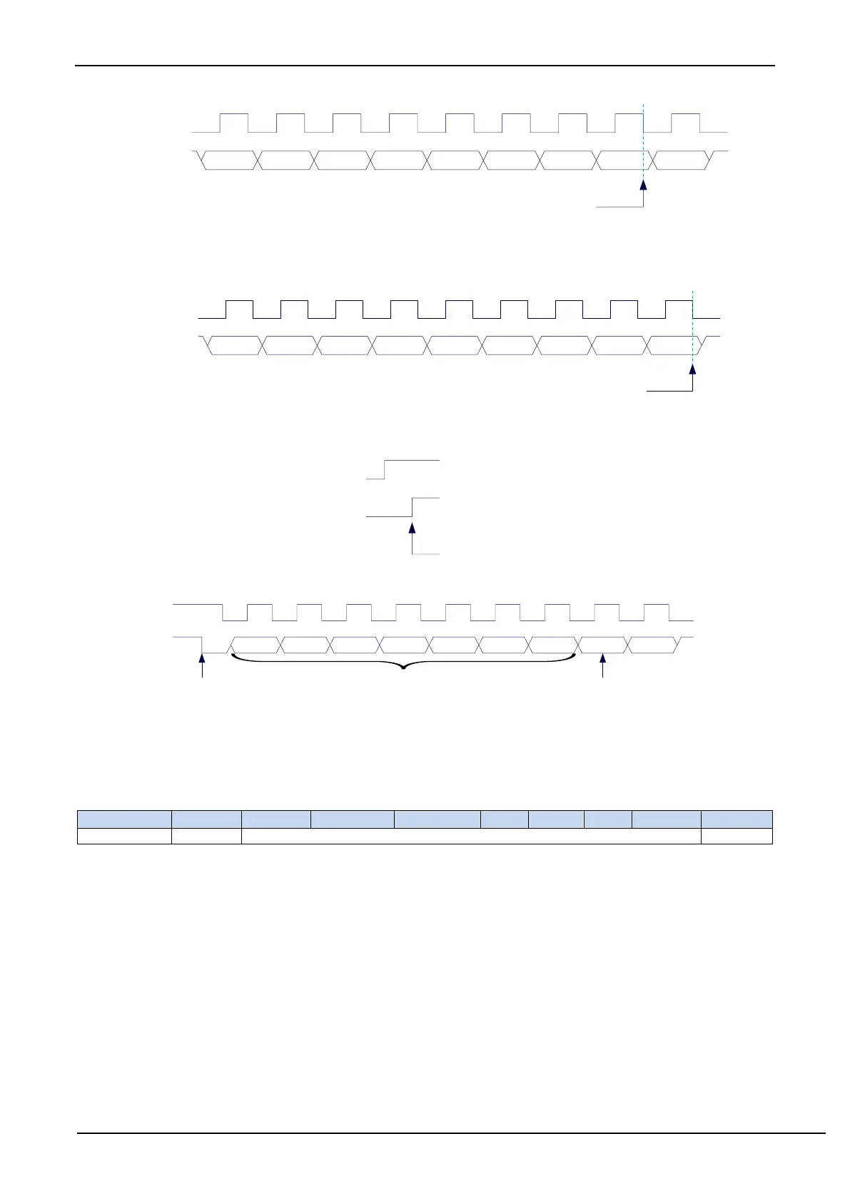
TXIF: interrupt request bit after 1-byte datum transmission is completed in slave mode. After the I
2
C controller in slave
mode completes sending 1 byte of datum and receives a 1-bit ACK signal successfully, this bit is set by hardware
automatically at the falling edge of the 9
th
clock and requests an interrupt to CPU. TXIF bit must be cleared by
software after the interrupt is responded. The time point of TXIF being set is shown below:
STOIF: interrupt request bit after STOP signal is received in slave mode. After the I
2
C controller in slave mode receives
the STOP signal, this bit is set by hardware automatically and requests interrupt to CPU. The STOIF bit must be
cleared by software after the interrupt is serviced. The time point of STOIF being set is shown below:
I2CSLADR[7:1]: the slave device address
When the I
2
C controller is in slave mode, the controller will continue to detect the device address and read / write
signals sent by the master after it receives the START signal. If the device address sent by the master matches
the slave device address set in SLADR[6: 0], the controller will request an interrupt to CPU to process the I
2
C
event. Otherwise, if the device address does not match, the I
2
C controller continues to monitor, wait for the
next START signal, and match the next device address.
MA: Slave device address matching control bit
0: The device address must be the same as I2CSLADR[7:1].
1: Ignore the settings in I2CSLADR[7:1] and match all device addresses.
Note: The I2C bus protocol stipulates that a maximum of 128 I2C devices (theoretical value) can be mounted on
the I2C bus, and different I2C devices are identified by different I2C slave device addresses. After the I2C
master sends the start signal, the upper 7 bits of the first data (DATA0) sent are the slave device address
(DATA0[7:1] is the I2C device address), and the lowest bit is the read and write signal. When the I2C device