STC8A8K64D4 Series Manual
17 ADC, Internal Reference Voltage
A 12-bit high-speed Analog to Digital Converter is integrated in STC8A8K64D4 family of microcontrollers. The
system frequency is divided by 2 and then divided again by the user-set division ratio as the clock frequency of the
ADC. The range of ADC clock frequency is SYSclk/2/1 ~ SYSclk/2/16.
The fastest ADC speed of STC8A8K64D4 series: 12-bit ADC is 800K (800,000 ADC conversions per second).
There are two data formats for ADC conversion results: Align left and Align right. It is convenient for user program
to read and reference.
Note: The 15th channel of the ADC can only be used to detect the internal reference voltage. The reference voltage
value is calibrated to 1.19V at the factory. Due to the manufacturing errors and measurement errors, the actual internal
reference voltage has about ±1% error compared to 1.19V. If you want to know the exact internal reference voltage of
each chip, you can connect an accurate reference voltage and then use the 15
th
channel of the ADC to measure the
calibration.
If the chip has ADC external reference power supply pin ADC_Vref+, it must not be floating, it must be connected
to an external reference power supply or directly connected to VCC
17.1 Registers Related to ADC
ADC Configuration Register
ADC Timing Control Register
ADC Extended configuration
registers
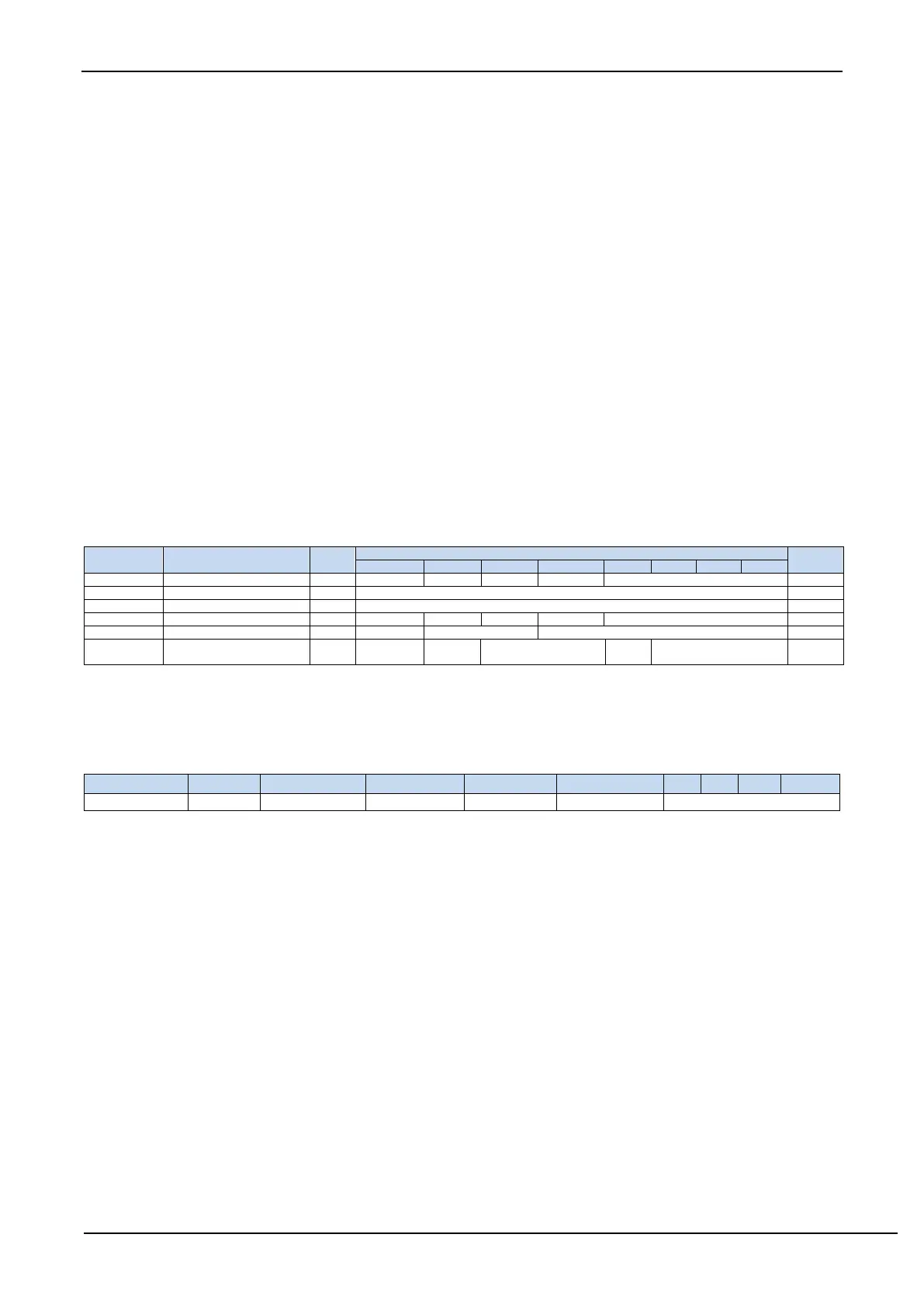
17.1.1 ADC control register (ADC_CONTR)
ADC_POWER: ADC power supply control bit.
0: turn off the power supply of ADC.
1: turn on the power supply of ADC.
It is recommended to turn off the ADC before entering Idle mode and Power-down mode to reduce the power
consumption.
Pay attention:
1. After the power supply to the internal ADC module of the MCU is turned on, wait for about 1ms, and wait for
the ADC power supply inside the MCU to stabilize before allowing the ADC to work;
2. Properly lengthening the sampling time of the external signal is the charging or discharging time of the internal
sampling and holding capacitor of the ADC. If the time is enough, the internal can be equal to the external potential.
ADC_START: ADC start bit. ADC conversion will start after write 1 to this bit. It is cleared automatically by the
hardware after A/D conversion completes.
0: no effect. Writing 0 to this bit will not stop the A/D conversion if the ADC has already started.
1: start the A/D conversion. It is cleared automatically by the hardware after A/D conversion completes.
ADC_FLAG: ADC conversion completement flag. It is set by the hardware after the ADC conversion hasfinished, and
requests interrupt to CPU. It must be cleared by software.
ADC_EPWMT: enable PWM synchronous trigger ADC function.
ADC_CHS[3:0]: ADC anolog channel selection bits.
(Note: The I/O port selected as the ADC input channel must be set to the PxM0/PxM1 register to set the I/O port
mode to high-impedance input mode. In addition, if the MCU enters the power-down mode/clock stop mode,