STC8A8K64D4 Series Manual
21.4 I
2
C Slave Mode
21.4.1 I
2
C Slave Control Register (I2CSLCR)
ESTAI: interrupt enable bit when receiving START signal in slave mode.
0: disable interrupt when receiving START signal in slave mode.
1: enable interrupt when receiving START signal in slave mode.
ERXI: interrupt enable bit after 1 byte datum is received in slave mode
0: disable interrupt after a datum is received in slave mode.
1: enable interrupt after 1 byte datum is reveived in slave mode.
ERXI: interrupt enable bit after 1 byte datum is sent in slave mode
0: disable interrupt after a datum is sent in slave mode.
1: enable interrupt after 1 byte datum is sent in slave mode.
ESTOI: interrupt enable bit after STOP signal is received in slave mode.
0: disable interrupt after STOP signal is received in slave mode.
1: enable interrupt after STOP signal is received in slave mode.
SLRST: reset slave mode
21.4.2 I
2
C Slave Status Register (I2CSLST)
SLBUSY: status bit of I
2
C controller in slave mode. (Read-only)
0: the controller is in idle state.
1: the controller is in busy state.
When the I
2
C controller is in slave mode, the controller will continue to detect the subsequent device address data
when it receives the START signal from the master in idle state. If the device address matches the slave address
set in the current I2CSLADR register, the controller will enter the busy state. And the busy state will be
maintained until receives a STOP signal sent by the master successfully, and then the state will return to idle.
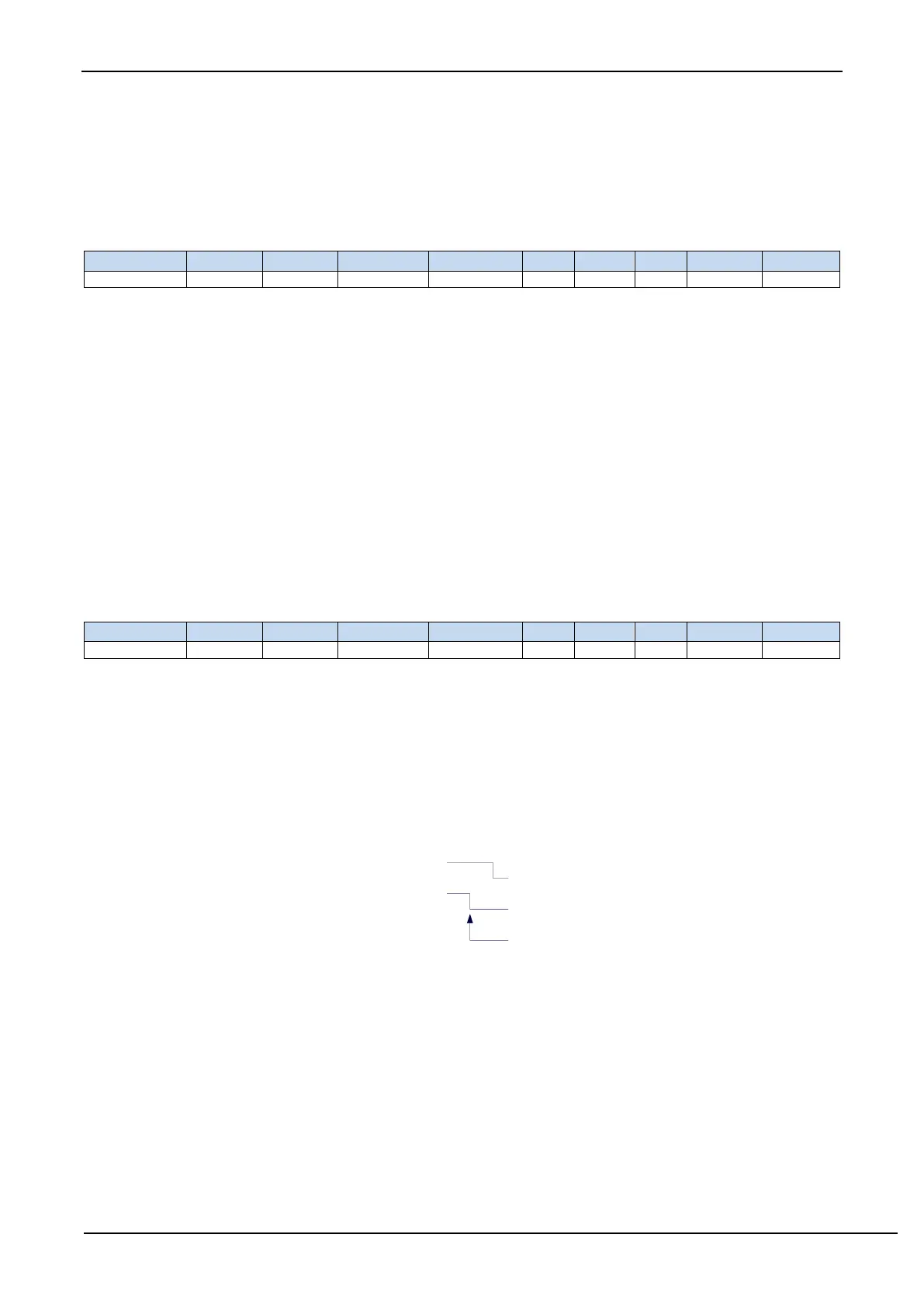
STAIF: interrupt request bit after START signal is received in slave mode. After the I
2
C controller in slave mode
receives the START signal, this bit is set by hardware automatically and requests interrupt to CPU. The STAIF bit
must be cleared by software after the interrupt is responded. The time point of STAIF being set is shown below:
SCL
SDA
(input)
STAIF is set
to 1 here
RXIF: interrupt request bit after 1-byte datum is received in slave mode. After the I
2
C controller in slave mode receives
a 1-byte datum, this bit is set by hardware automatically at the falling edge of the 8th clock and will request
interrupt to CPU. The RXIF bit must be cleared by software after the interrupt is responded. The time point of
RXIF being set is shown in the figure below: