Timer/counter 0 mode 3: 16-bit auto-reload mode with non-maskable interrupt
Note: When Timer/Counter 0 works in mode 3 (16-bit auto-reload mode with non-maskable interrupt), it is not
necessary to enable EA/IE.7 (total interrupt enable bit), only ET0/IE.1 is required. (Timer/counter 0 interrupt enable
bit) can turn on the timer/counter 0 interrupt. The timer/counter 0 interrupt in this mode has nothing to do with the total
interrupt enable bit EA. Once the timer/counter 0 interrupt in this mode is enabled, the timer/counter 0 interrupt priority
is the highest, and it cannot be interrupted by any other interrupt (no matter it is lower than the timer/counter 0 interrupt
priority). After the interrupt in this mode is enabled, it is neither controlled by EA/IE.7 nor controlled by ET0. Clearing
EA nor ET0 can not disable this interrupt.
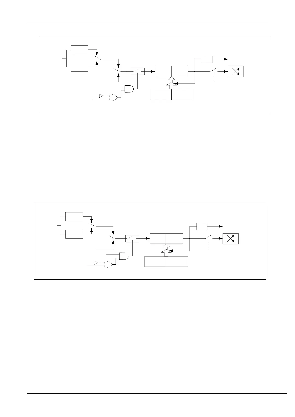
13.2.7 Timer 1 mode 0 (16-bit auto-reloadable mode)
In this mode, Timer/Counter 1 is used as a 16-bit counter that can be automatically reloaded, as shown in the figure
below.
Timer/Counter 1 mode 0: 16-bit auto-reload mode
When GATE=0 (TMOD.7), the timer will count if TR1=1. When GATE=1, it is allowed to control timer1 by
external input INT1, so that pulse width measurement can be realized. TR1 is the control bit in the TCON register. For
the specific function description of each bit of the TCON register, see the introduction of the TCON register in the
previous section.
When C/T=0, the multiplexer is connected to the frequency division output of the system clock. T1 counts the
internal system clock, and works in timing mode. When C/T=1, the multiplexer is connected to the external pulse input
P3.5/T1, and T1 works in counting mode.
Timer1 of STC microcontroller has two counting rates: one is 12T mode, which is increased by 1 for every 12
clocks, which is the same as traditional 8051 microcontroller, the other is 1T mode, which is increased by 1 for each
clock, and the speed is 12 times of traditional 8051. The rate of T1 is determined by T1x12 in the special function
register AUXR. If T1x12=0, T1 works in 12T mode, and if T1x12=1, T1 works in 1T mode.
Timer1 has two hidden registers RL_TH1 and RL_TL1. RL_TH1 and TH1 share the same address, and RL_TL1
and TL1 share the same address. When TR1=0, that is, when Timer/Counter1 is disabled, the content written to TL1
will be written to RL_TL1 at the same time, and the content written to TH1 will also be written to RL_TH1 at the same