STC8A8K64D4 Series Manual
CCAPNn: PCAn Capture on falling edge enable bit
MATn: PCAn match function enable bit
TOGn: PCAn high speed pulse output function enable bit
PWMn: PCAn PWM output function enable bit
ECCFn: PCAn match/capture interrupt enable bit
18.2.5 PCA capture value/compare value registers (CCAPnL, CCAPnH)
When the PCA capture function is enabled, CCAPnL and CCAPnH are used to save the count value (CL and CH) of
the PCA at the time of capture. When the PCA comparison function is enabled, the PCA controller compares the
current value in [CH,CL] and the value in [CCAPnH, CCAPnL], and the comparison result is given. When the
PCA match function is enabled, the PCA controller compares the current value in [CH, CL] with the value stored
in [CCAPnH, CCAPnL], and checks if they match (equal), then gives a match result.
18.2.6 PCA PWM mode control registers (PCA_PWMn)
EBSn[1:0]: PCAn PWM number of bits control
{EPCnH, XCCAPnH[1:0], CCAPnH[7:0]}
{EPCnL, XCCAPnL[1:0], CCAPnL[7:0]}
XCCAPnH[1:0]: The 9
th
bit and 10
th
bit of reload value of 10-bit PWM
XCCAPnL[1:0]: The 9
th
bit and 10
th
bit of comparison value of 10-bit PWM
EPCnH: The MSB of reload vaule in PWM mode (i.e. the 9
th
bit of 8-bit PWM, the 8
th
bit of 7-bit PWM, the 7
th
bit of 6-bit PWM, the 11
th
bit of 10-bit PWM)
EPCnL: The MSB of comparison vaule in PWM mode (i.e. the 9
th
bit of 8-bit PWM, the 8
th
bit of 7-bit PWM, the
7
th
bit of 6-bit PWM, the 11
th
bit of 10-bit PWM)
Note: When updating the reload value of 10-bit PWM, write the upper two bits of XCCAPnH [1: 0] firstly and
then the lower 8 bits of CCAPnH [7: 0].
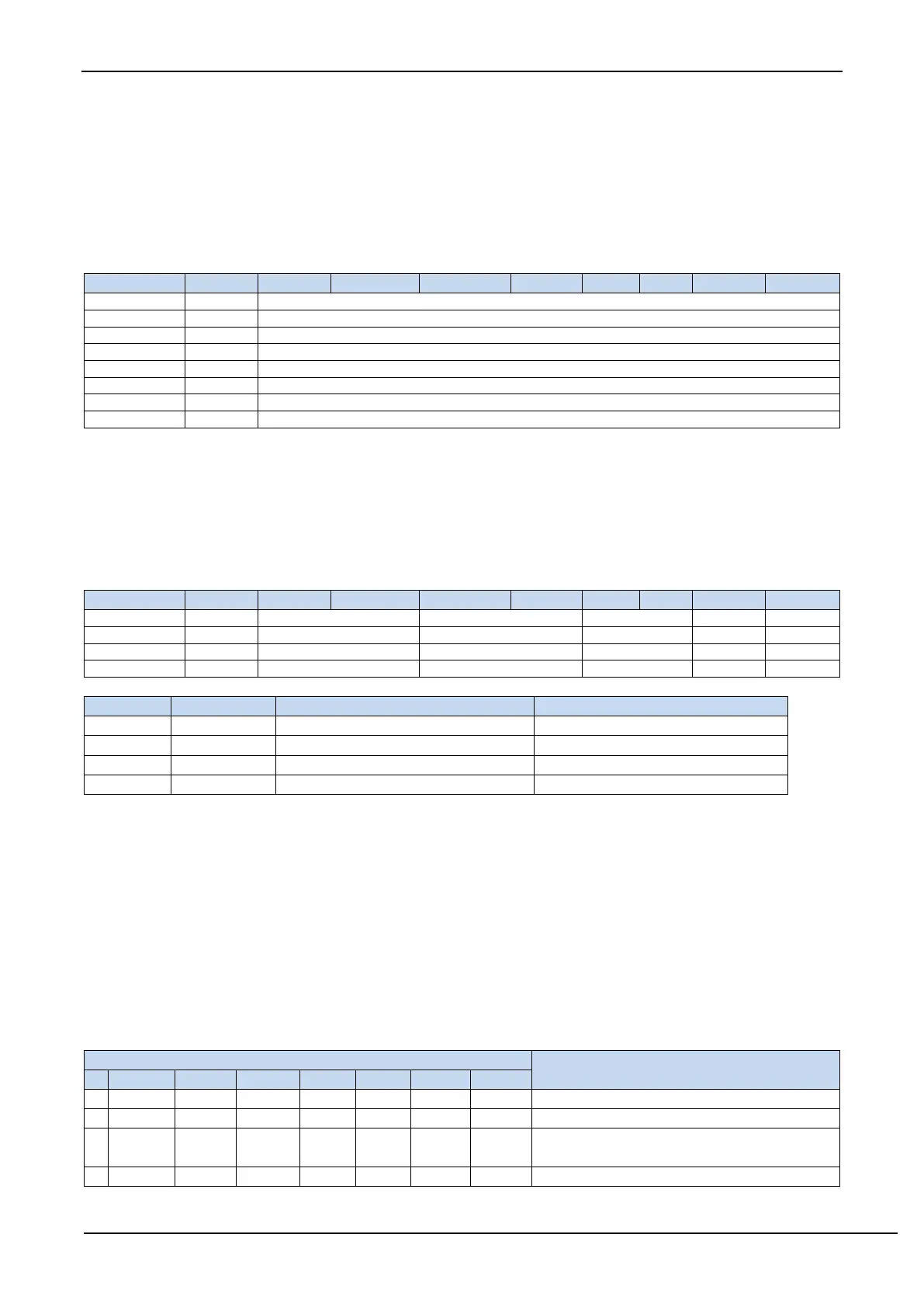
18.3 PCA Operation Mode
There are 4 groups of PCA modules in STC12Hseries of microcontrollers, and operation mode of each module can be
set independently. The mode settings are as follows:
6/7/8/10 bit PWM mode, no interrupt
6/7/8/10 bit PWM mode, rising edge
interrupt
6/7/8/10 bit PWM mode, falling edge