STC8A8K64D4 Series Manual
13.2.12 Auxiliary Register 1 (AUXR)
T0x12: T0 speed control bit.
0: The clock source of T0 is SYSclk/12.
1: The clock source of T0 is SYSclk/1.
T1x12: T1 speed control bit.
0: The clock source of T1 is SYSclk/12.
1: The clock source of T1 is SYSclk/1.
13.2.13 External Interrupt and Clock Output Control Register
(INTCLKO)
T0CLKO: T0 clock out control bit.
0: Turn off the clock output.
1: P3.5 is configured for T0 clock output pin. When T0 overflows, P3.5 will flip automatically.
T1CLKO: T0 clock out control bit.
0: Turn off the clock output.
1: P3.4 is configured for T1 clock output pin. When T1 overflows, P3.4 will flip automatically.
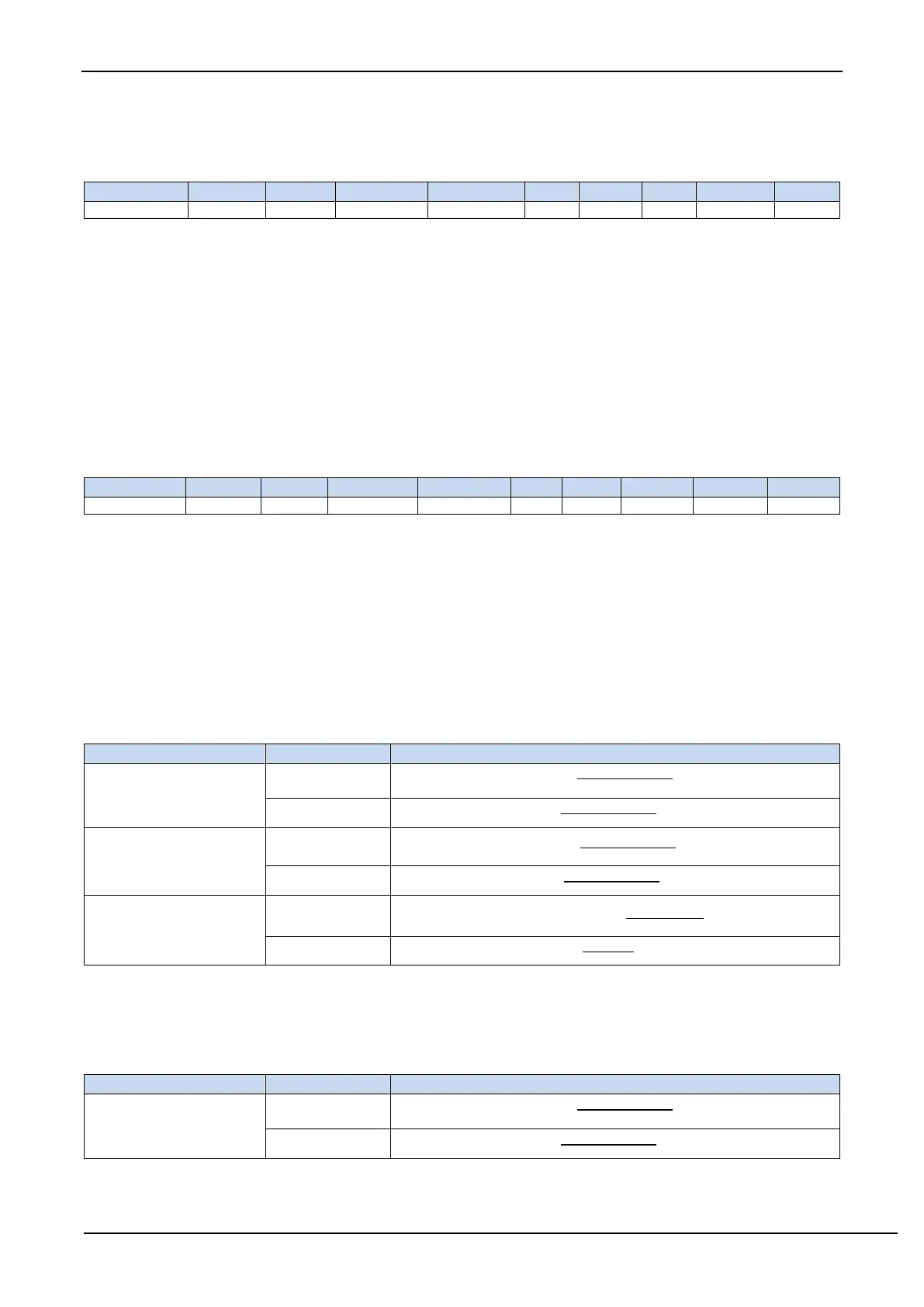
13.2.14 Timer 0 calculation formula
Period calculation formula
Mode 0/3
(16-bit automatic reload)
(Auto-reload)
(Auto-reload)
Mode 1
(16-bit does not
automatically reload)
(Soft reload)
(Soft reload)
Mode 2
(8-bit automatic reload)
(Auto-reload)
13.2.15 Timer 1 calculation formula
Period calculation formula
Mode 0
(16-bit automatic reload)
(Auto-reload)
(Auto-reload)