STC8A8K64D4 Series Manual
15.3 Registers Related to Comparator
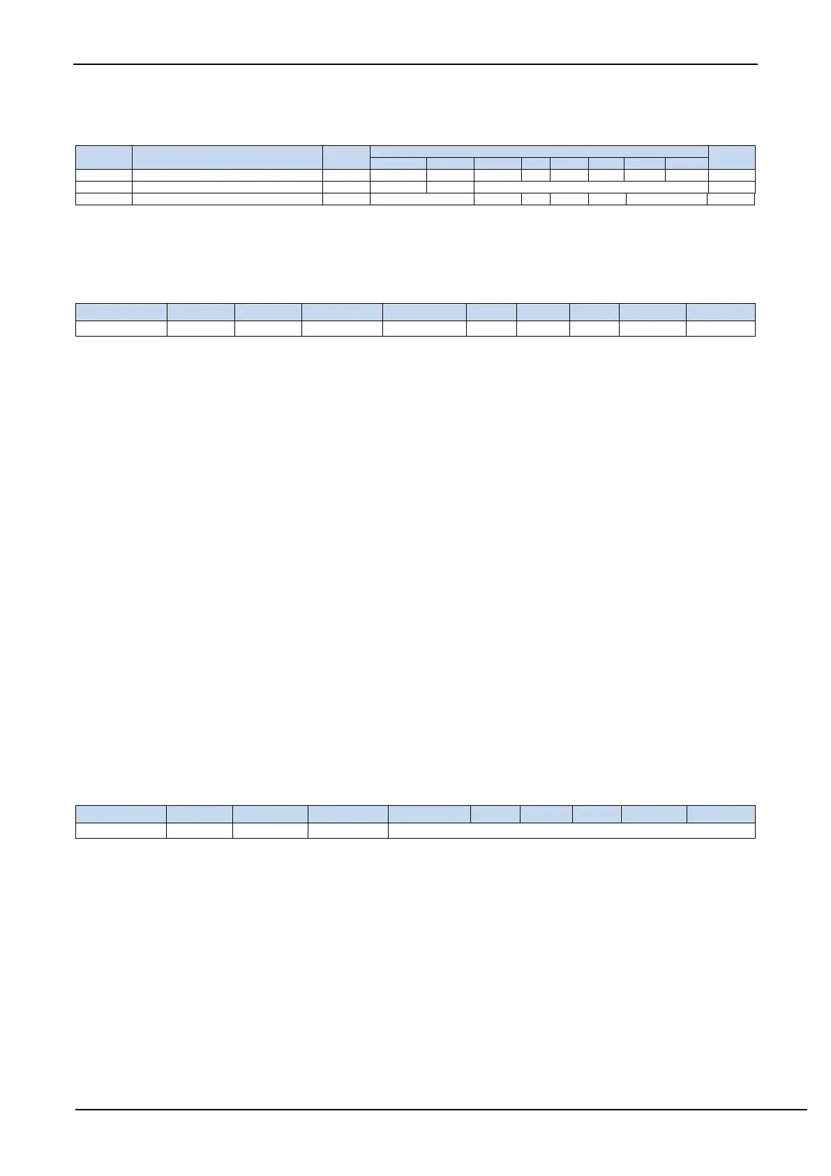
Comparator Control Register 1
Comparator Control Register 2
Comparator Extended Configuration Register
15.3.1 Comparator control register 1
CMPEN: Comparator enable bit
0: disable comparator
1: enable comparator
CMPIF: Comparator interrupt flag. When PIE or NIE is enabled, if the corresponding interrupt signal is generated, the
hardware will automatically set CMPIF and request interrupt to CPU. This flag must be cleared by software. (Note:
When the comparator interrupt is not enabled, this interrupt flag will not be set by the hardware, that is,
this interrupt flag cannot be queried when the comparator is accessed in query mode.)
PIE: Comparator rising edge interrupt enable bit
0: disable comparator rising edge interrupt
1: enable comparator rising edge interrupt. Enable the interrupt request when the compare result of the comparator
changes from 0 to 1.
NIE: Comparator falling edge interrupt enable bit
0: disable comparator falling edge interrupt
1: enable comparator falling edge interrupt. Enable the interrupt request when the compare result of the comparator
changes from 1 to 0.
CMPOE: Comparator result output control bit
0: disable comparator result output.
1: enable comparator result output. The comparator result is output to P3.4 or P4.1, which is selected by CMPO_S
in P_SW2.
CMPRES: Flag bit of comparator result. (Read-only)
0: the level of CMP+ is lower than CMP-.
1: the level of CMP+ is higher than CMP-.
CMPRES is the digitally filtered output signal, not the comparator's direct output.
15.3.2 Comparator control register 2
INVCMPO: Inverse comparator output control bit
0: Normal output the result of comparator. If CMPRES is 0, P3.4 / P4.1 output low, and vice versa output high.
1: Output the result of comparator after it is inversed. If CMPRES is 0, P3.4 / P4.1 output high, and vice versa
output low.
DISFLT: Analog filtering function control bit
0: enable 0.1us analog filtering function
1: disable 0.1us analog filtering function, which can speed up the comparator slightly.
LCDTY[5:0]: Digital filtering function control bit
Digital filtering is the debouncing function of the digital signal. When the comparison result changes at the
rising edge or falling edge, the data changing is considered be valid only if the signal the comparator detected does
not change and maintains the number of CPU clocks set in LCDTY. Otherwise, the signal will be treated as no
change.
Note: When the digital filtering function is enabled, the actual waiting clock inside the chip needs to add two
additional state machine switching times, that is, if LCDTY is set to 0, the digital filtering function is turned off;