EasyManua.ls Logo

STC micro STC8A8K64D4 Series - Port Data Register (Px); Ports Mode Registers (Pxm0, Pxm1)

Default Icon
901 pages
Print Icon
To Next Page IconTo Next Page
To Previous Page IconTo Previous Page
Loading...
STC8A8K64D4 Series Manual
-
- 165 -
P2IE
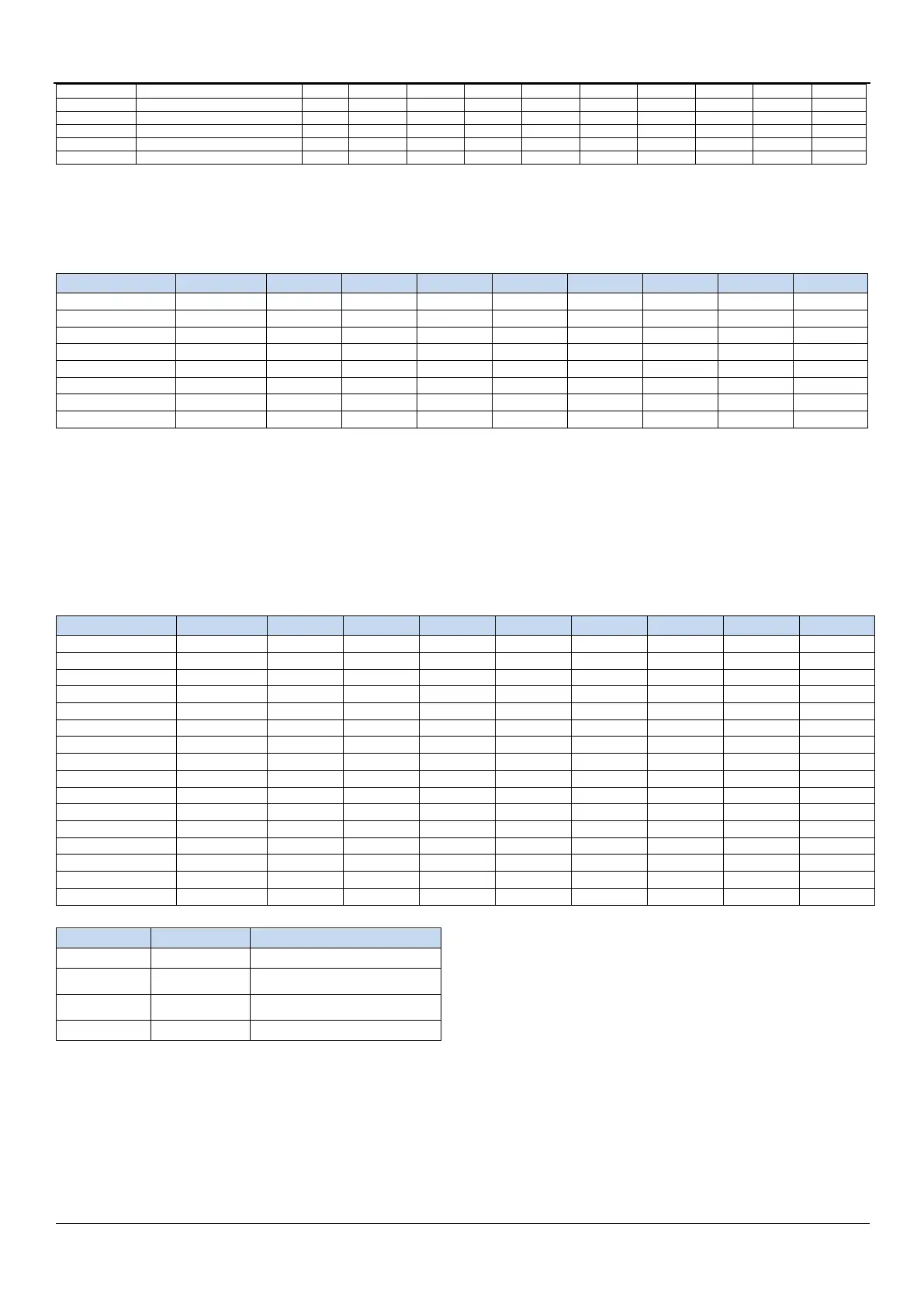
P2 Input Enable Control Register
FE32H
P27IE
P26IE
P25IE
P24IE
P23IE
P22IE
P21IE
P20IE
1111,1111
P3IE
P3 Input Enable Control Register
FE33H
P37IE
P36IE
P35IE
P34IE
P33IE
P32IE
P31IE
P30IE
1111,1111
P4IE
P4 Input Enable Control Register
FE34H
P47IE
P46IE
P45IE
P44IE
P43IE
P42IE
P41IE
P40IE
1111,1111
P5IE
P5 Input Enable Control Register
FE35H
-
-
P55IE
P54IE
P53IE
P52IE
P41IE
P50IE
xx11,1111
P6IE
P6 Input Enable Control Register
FE36H
P67IE
P66IE
P65IE
P64IE
P63IE
P62IE
P41IE
P60IE
1111,1111
P7IE
P7 Input Enable Control Register
FE37H
P77IE
P76IE
P75IE
P74IE
P73IE
P72IE
P41IE
P70IE
1111,1111
9.1.1 Port Data Register (Px)
Symbol
Address
B7
B6
B5
B4
B3
B2
B1
B0
P0
80H
P0.7
P0.6
P0.5
P0.4
P0.3
P0.2
P0.1
P0.0
P1
90H
P1.7
P1.6
P1.5
P1.4
P1.3
P1.2
P1.1
P1.0
P2
A0H
P2.7
P2.6
P2.5
P2.4
P2.3
P2.2
P2.1
P2.0
P3
B0H
P3.7
P3.6
P3.5
P3.4
P3.3
P3.2
P3.1
P3.0
P4
C0H
P4.7
P4.6
P4.5
P4.4
P4.3
P4.2
P4.1
P4.0
P5
C8H
-
-
P5.5
P5.4
P5.3
P5.2
P5.1
P5.0
P6
E8H
P6.7
P6.6
P6.5
P6.4
P6.3
P6.2
P6.1
P6.0
P7
F8H
P7.7
P7.6
P7.5
P7.4
P7.3
P7.2
P7.1
P7.0
Read and write port status
Write 0: Output low to port buffer.
Write 1: Output high to port buffer.
Read: Read the level on the port pin directly.
9.1.2 Ports Mode Registers (PxM0, PxM1)
Symbol
Address
B7
B6
B5
B4
B3
B2
B1
B0
P0M0
94H
P07M1
P06M1
P05M1
P04M1
P03M1
P02M1
P01M1
P00M1
P0M1
93H
P07M0
P06M0
P05M0
P04M0
P03M0
P02M0
P01M0
P00M0
P1M0
92H
P17M1
P16M1
P15M1
P14M1
P13M1
P12M1
P11M1
P10M1
P1M1
91H
P17M0
P16M0
P15M0
P14M0
P13M0
P12M0
P11M0
P10M0
P2M0
96H
P27M1
P26M1
P25M1
P24M1
P23M1
P22M1
P21M1
P20M1
P2M1
95H
P27M0
P26M0
P25M0
P24M0
P23M0
P22M0
P21M0
P20M0
P3M0
B2H
P37M1
P36M1
P35M1
P34M1
P33M1
P32M1
P31M1
P30M1
P3M1
B1H
P37M0
P36M0
P35M0
P34M0
P33M0
P32M0
P31M0
P30M0
P4M0
B4H
P47M1
P46M1
P45M1
P44M1
P43M1
P42M1
P41M1
P40M1
P4M1
B3H
P47M0
P46M0
P45M0
P44M0
P43M0
P42M0
P41M0
P40M0
P5M0
CAH
-
-
P55M1
P54M1
P53M1
P52M1
P51M1
P50M1
P5M1
C9H
-
-
P55M0
P54M0
P53M0
P52M0
P51M0
P50M0
P6M0
CCH
P67M0
P66M0
P65M0
P64M0
P63M0
P62M0
P61M0
P60M0
P6M1
CBH
P67M1
P66M1
P65M1
P64M1
P63M1
P62M1
P61M1
P60M1
P7M0
E2H
P77M0
P76M0
P75M0
P74M0
P73M0
P72M0
P71M0
P70M0
P7M1
E1H
P77M1
P76M1
P75M1
P74M1
P73M1
P72M1
P71M1
P70M1
Configure the mode of the ports as shown below.
PnM1.x
PnM0.x
Pn.x mode
0
0
quasi bidirectional mode
0
1
push-pull output mode
1
0
high-impedance input mode
1
1
open drain mode
Note: When an I/O port is selected as the ADC input channel, the PxM0/PxM1 register must be set to set the I/O port
mode to input mode. In addition, if the ADC channel still needs to be enabled after the MCU enters the power-down
mode/clock stop mode, you need to set the PxIE register to close the digital input to ensure that there will be no
additional power consumption.

Table of Contents

Related product manuals