STC8A8K64D4 Series Manual
6/7/8/10 bit PWM mode, rising and falling
edge interrup
16 bit rising edge capture mode
16 bit falling edge capture mode
16 bit rising and falling edge capture mode
16 bit software timer mode
16 bit high speed pulse output mode
18.3.1 Capture Mode
At least one of CAPNn and CAPPn bits in CCAPMn must be set (or all of them are set) for a PCA module to
operate in capture mode. When a PCA module is operating in capture mode, the input hoppings on the external
CCP0/CCP1/CCP2 pins of the module are sampled. When a valid hopping is sampled, the PCA controller immediately
loads the counter values in the PCA counters, CH and CL, into the module’s capture registers, CCAPnL and CCAPnH,
and sets the corresponding CCFn in the CCON register. If the ECCFn bit in CCAPMn is set to 1, an interrupt will be
generated. Since all PCA modules’ interrupt entry addresses are shared, it is necessary to determine which module
generated an interrupt in the interrupt service routine and note that the interrupt flag bit must be cleared by software.
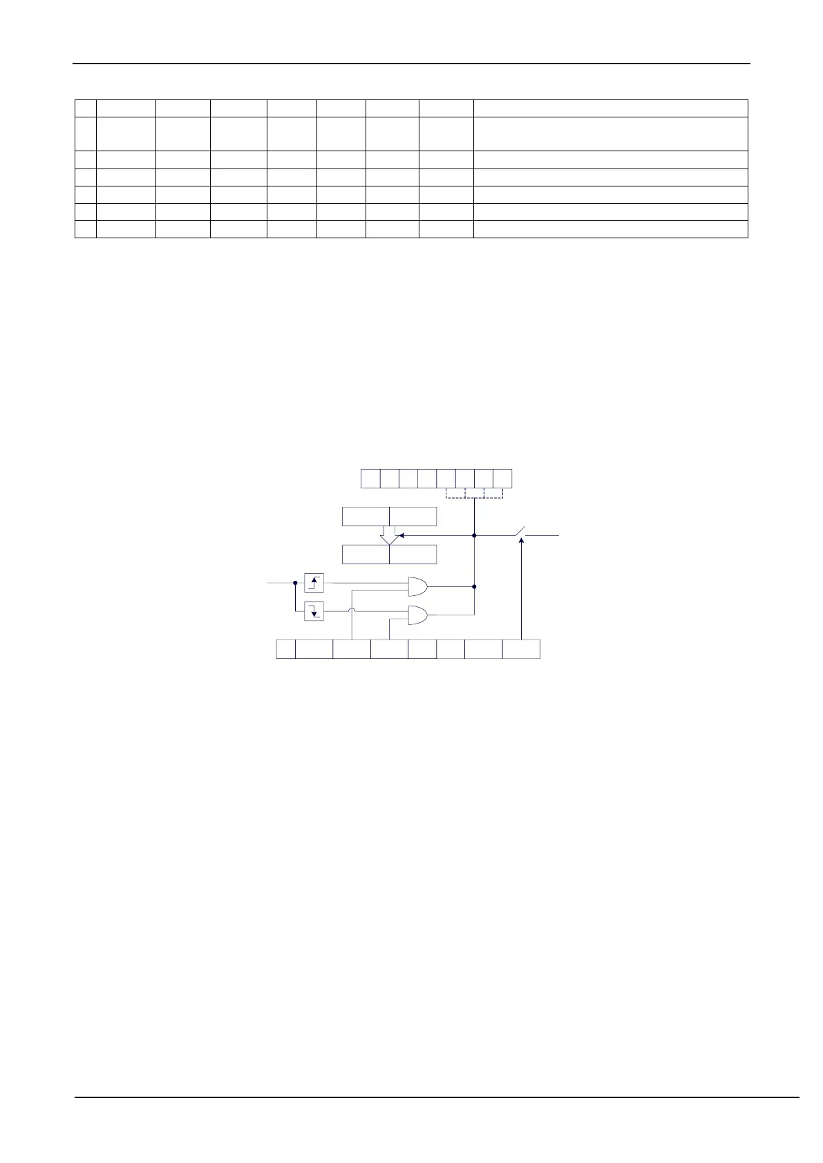
The structure of the PCA module working in capture mode is shown in the following figure.
PCA capture mode
PCA
interrupt
0 0 0 0 0
CCAPMn
- ECOMn CAPPn CAPNn MATn TOGn PWMn ECCFn
CF CR - - CF3CF2CF1CF0
CCON
CH CL
CCAPnH CCAPnL
CCP0
CCP1
CCP2
CCP3
18.3.2 Software Timer Mode
The PCA module can be used as a software timer by setting the ECOM and MAT bits in the CCAPMn register.
The PCA counter value in CL and CH is compared with the capture registers value in CCAPnL and CCAPnH. When
they are equal, CCFn in CCON is set and an interrupt is generated if ECCFn in CCAPMn is set to 1. CCFn flag bit
should be cleared by software.
The structure of PCA module working in software timer mode is shown in the following figure.