STC8A8K64D4 Series Manual
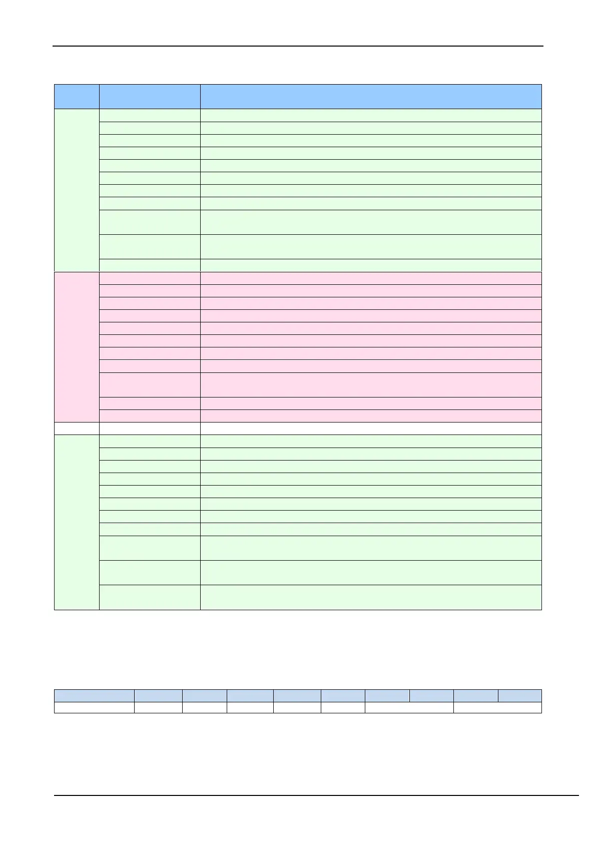
high byte of the 1st ADC conversion result of the 1st enabled channel
low byte of the 1st ADC conversion result of the 1st enabled channel
high byte of the 2nd ADC conversion result of the 1st enabled channel
low byte of the 2nd ADC conversion result of the 1st enabled channel
high byte of the nth ADC conversion result of the 1st enabled channel
low byte of the nth ADC conversion result of the 1st enabled channel
ADC channel number of 1st channel
remainder after the average value of the n ADC conversion results of the 1st
channel
high byte of the average value of the n ADC conversion results of the 1st
channel
low byte of the average value of the n ADC conversion results of the 1st channel
high byte of the 1st ADC conversion result of the 2nd enabled channel
low byte of the 1st ADC conversion result of the 2nd enabled channel
high byte of the 2nd ADC conversion result of the 2nd enabled channel
low byte of the 2nd ADC conversion result of the 2nd enabled channel
high byte of the nth ADC conversion result of the enabled 2nd channel
low byte of the nth ADC conversion result of the enabled 2nd channel
ADC channel number of 2nd channel
remainder after the average value of the n ADC conversion results of 2nd
channel
high byte of the average value of n ADC conversion results of 2nd channel
low byte of the average value of n ADC conversion results of 2nd channel
high byte of the 1st ADC conversion result of the enabled mth channel
low byte of the 1st ADC conversion result of the enabled mth channel
high byte of the 2nd ADC conversion result of the enabled mth channel
low byte of the 2nd ADC conversion result of the enabled mth channel
high byte of the nth ADC conversion result of the enabled mth channel
low byte of the nth ADC conversion result of the enabled mth channel
ADC channel number of the mth channel
remainder after the average value of the n ADC conversion results of the mth
channel
high byte of the average value of the n ADC conversion results of the mth
channel
low byte of the average value of the n ADC conversion results of the mth
channel
23.4 Data exchange between SPI and memory (SPI_DMA)
23.4.1 SPI_DMA Configuration Register(DMA_SPI_CFG)
SPIIE: SPI_DMA interrupt enable control bit
0: Disable SPI_DMA interrupt
1: Enable SPI_DMA interrupt
ACT_TX: SPI_DMA transmit data control bit