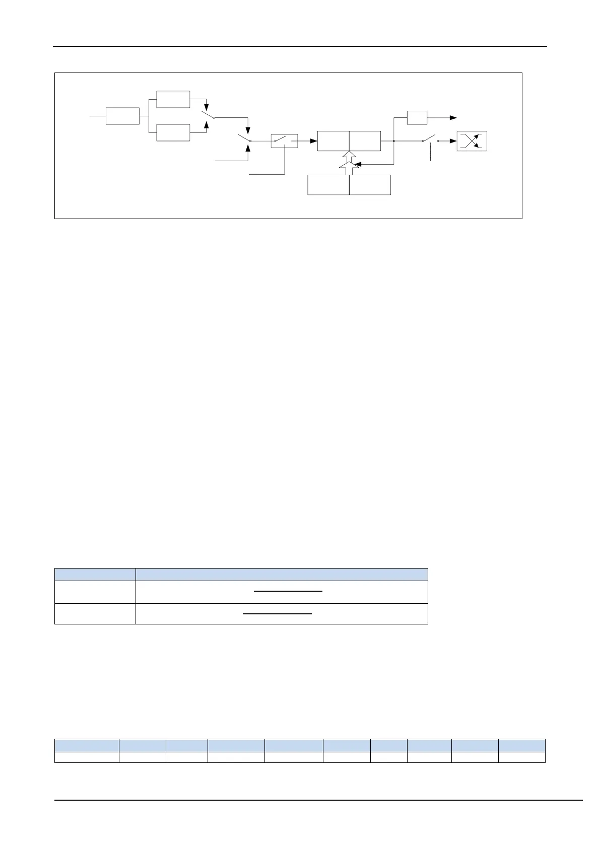
Timer/counter 2 working mode: 16-bit auto-reload mode
T2R/AUXR.4 is the control bit in the AUXR register. For the specific function description of each bit of the
AUXR register, see the introduction of the AUXR register in the previous section.
When T2_C/T=0, the multiplexer is connected to the frequency division output of the system clock, T2 counts the
internal system clock, and works in timing mode. When T2_C/T=1, the multiplexer is connected to the external pulse
input T2, and T2 works in counting mode.
Timer2 of STC microcontroller has two counting rates: one is 12T mode, which is increased by 1 for every 12
clocks, which is the same as traditional 8051 microcontroller, the other is 1T mode, which is increased by 1 for each
clock, and the speed is 12 times of traditional 8051. The rate of T2 is determined by T2x12 in the special function
register AUXR. If T2x12=0, T2 works in 12T mode, and if T2x12=1, T1 works in 1T mode.
Timer2 has two hidden registers RL_T2H and RL_T2L. RL_T2H and T2H share the same address, and RL_T2L
and T2L share the same address. When T2R=0, that is, when Timer/Counter2 is disabled, the content written to T2L
will be written to RL_T2L at the same time, and the content written to T2H will also be written to RL_T2H at the same
time. When T2R=1, that is, when Timer/Counter2 starts to work, writing content to T2L is not actually written to the
current register T2L, but written to the hidden register RL_T2L, and writing content to T2H is actually also it is not
written into the current register T2H, but into the hidden register RL_T2H, which can cleverly realize the 16-bit reload
timer. When reading the contents of T2H and T2L, the contents be read are the contents of T2H and T2L, not the
contents of RL_T2H and RL_T2L.
The overflow of [T2H, T2L] not only sets the interrupt request flag (T2IF), which causes the CPU to switch to
the timer 2 interrupt routine, but also automatically reloads the contents of [RL_T2H, RL_T2L] into [T2H, T2L].
13.3.6 Timer 2 calculation formula