STC8A8K64D4 Series Manual
0: PWMFLT level is not associated with PWM
1: the source of PWM fault detection is PWMFLT. (The fault type is set by INVIO.)
FDIF: the interrupt flag bit of PWM fault detection.
It is set automatically by the hardware when a PWM fault occurs. If EFDI=1, the program will jump to the
corresponding interrupt entry to execute interrupt service routine. It should be cleared by software.
19.2.5 PWM Counter Registers (PWMCH, PWMCL)
PWMCH: upper 7 bits of PWM counter period value.
PWMCL: lower 8 bits of PWM counter period value.
The PWM counter is a 15-bit register that can be set to any value between 1 and 32767 as the PWM cycle. The counter
inside the PWM waveform generator counts from 0 and increments by 1 every PWM clock cycle. When the
internal counter reaches the PWM cycle set by [PWMCH, PWMCL], the internal counter of the PWM waveform
generator will count from 0 again, and the PWM return-to-zero interrupt flag bit PWMCBIF will be set by
hardware automatically. If ECBI = 1, the program will jump to the corresponding interrupt entry address to execute
the interrupt service routine.
19.2.6 PWM Clock Selection Register (PWMCKS)
SELT2: PWM clock source selection bit.
0: The PWM clock source is the clock generated by the system clock being divided by the frequency divider.
1: The PWM clock source is the overflow pulse of timer 2.
PWM_PS[3:0]: System clock prescaler parameter select bits
PWM input clock frequency
Overflow pulse of Timer 2
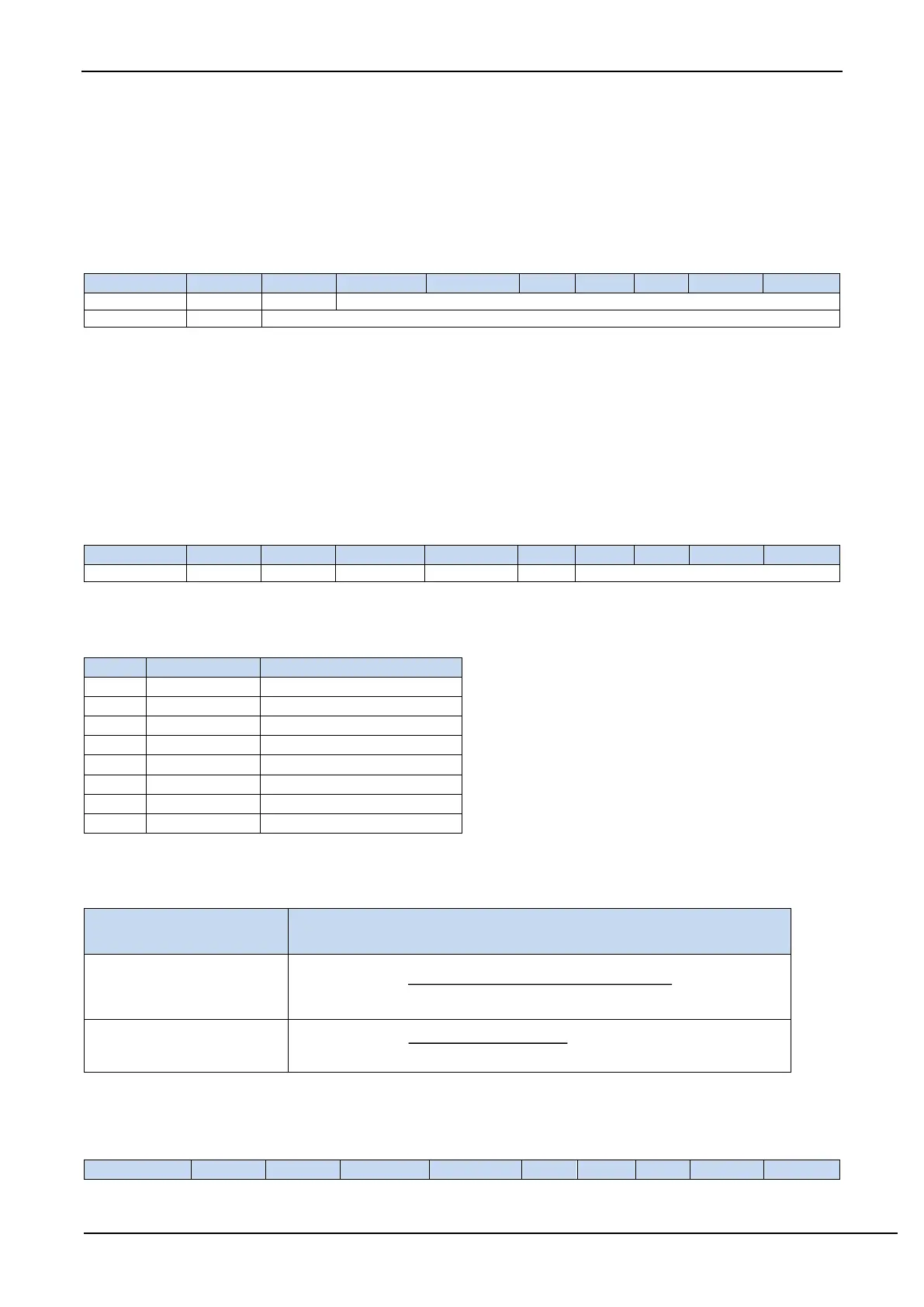
PWM output frequency calculation formula
The output frequency calculation formula of the 6 groups of PWM is the same, and each group can be set with a different
frequency.
Clock source selection
(SELT2)
PWM output frequency calculation formula
PWM output
frequency
System operating frequency SYSclk
(PWM_PS + 1)×( [PWMCH, PWMCL] + 1)
=
SELT2
=
1
(Timer 2 overflow pulse)
PWM output
frequency
Timer 2 overflow pulse frequency
( [PWMCH, PWMCL] + 1)
=
19.2.7 PWM Trigger ADC counter Registers (PWMTADC)